 |
Section 4 - Continued
Chemical Recovery
4.5.4 Technology/Equipment Description
This subsection contains names and/or descriptions of commercially available electrowinning equipment that is manufactured and/or sold by vendor survey respondents or discussed in the literature. This is intended to provide the reader with information and data on a cross section of available equipment. Mention of trade names or commercial products is not intended to constitute endorsement for use.
4.5.4.1 General
The typical electrowinning system consists of a tank that holds the electrolyte, sets of anodes and cathodes, a pump for transferring solutions from a feed tank to the electrolyte tank, rectifier, and controls.
Most electrolyte tanks are manufactured from polypropylene, although one of the surveyed manufacturers (ref. Eco-Tec file) also used lined steel tanks. The tanks range in size from approximately 10 to 1,500 gal. Rectifier output amperage ranges from approximately 25 to 5,000 amps (ref. vendor files), with the smallest units used primarily for precious metals (e.g., Au, Ag, Rh) recovery (ref. vendor files and 111).
The three most common types of electrolytic metal recovery equipment use either: (1) parallel flat plate cathodes, (2) reticulate cathodes; and (3) fibrous or high surface area cathodes. Generally, the parallel flat plate cathode units are used with concentrated metal solutions, the reticulate cathode units work over a wide range of concentrations, and high surface area cathode units are used exclusively with solutions containing dilute metal concentrations.
Various materials are used in the fabrication of anodes and cathodes. Until the 1960's, graphite and lead alloys were the most preferred anode materials. However, their high overpotential requirement and degradable nature presented significant drawbacks. More recently, anodes are commonly being manufactured of titanium and niobium and coated using the solid phase roll bonding method with precious metals, metallic oxides and/or their alloys and fluoride resistant metal composites (ref. 128). These types of electrodes are generically referred to as dimensionally stable anodes. The advantages of the newer anodes over the lead alloy anodes include: (1) produce higher purity product (deposit); (2) low oxygen overpotential increases current efficiency; and (3) corrosion resistance provides higher durability and stability.
Most commonly, flat plate, wire mesh and expanded metal cathodes are fabricated from stainless steel, reticulate cathodes are metal coated foam and high surface area cathodes are fabricated from carbon fibers. Additional details of cathode design are discussed in Sections 4.5.4.2 through 4.5.4.4.
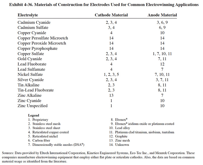 |
Exhibit 4-36 indicates the different materials used for electrode fabrication by the four manufacturers that responded to the Vendors Survey for their most common applications. It also includes other types of materials identified in the literature and known to be in common use.
4.5.4.2 Flat Plate Cathode Units
The flat plate design is often referred to as the conventional method of electrowinning because of its long standing role in the plating industry as well as other industries. Conventional electrowinning equipment is found in a variety of configurations. The basic design consists of a tank containing alternating flat sheets of cathodes and anodes. Commercially available electrolytic recovery units, used for waste treatment and recovery, have total cathode surface areas ranging from 1 ft2 to 200 ft2. Such units are extremely small in comparison to those used for primary copper production. An average copper refinery producing 500 tons per day of copper utilizes approximately 2.6 million square feet of total electrode area (ref. 349). A packaged recovery unit generally is supplied with a reactor tank or cell, copper bussing, cathodes, anodes, rectifier, current controller, recirculation pump, internal piping, and valves.
With the parallel flat plate electrode units, the recovered metal is removed in strips or slabs and can be sold to a refiner or used in-house by electroplaters as an anode material. Several variations of the conventional electrowinning process are used. Variations in design are typically aimed at overcoming electrode polarization and low ion diffusion rates which reduce recovery rates in low concentration solutions. This is typically achieved by reducing the thickness of the diffusion layer through agitation of the solution or movement of the cathode.
Flat plate electrowinning units are usually operated on a batch basis, although continuous configurations are also in use. With a batch operation, a solution containing metal ions is added to the electrowinning cell tank or continuously circulated from a side tank and a D.C. electrical current is applied. As the recovery process proceeds, metal ions are plated onto the cathode and the solution becomes depleted. Typically this process is halted when the deposition rate drops below a given point or when the metal deposit thickness reaches approximately 1/4 to 3/8 inch. The plated metal sheets can then be pealed from the cathode and reused or sold. It is possible for the plated deposit to envelop the cathode, making removal nearly impossible. This problem can be overcome by employing a technique termed current shadowing that gradually reduces the current density at the outer edges of the cathode plate. Another method is to use non-conductive edge strips. However this may result in the production of dendrites at the juncture of the edge-strips (ref. 349).
4.5.4.3 Wire Mesh, Expanded Metal and Reticulate Cathode Units
The wire mesh, expanded metal and reticulate cathode designs are aimed at increasing the surface area of the cathode. The wire mesh and expanded metal (appearance of floor grating) types are usually fabricated from stainless steel.
Reticulate is a term used by at least one manufacturer of electrowinning units to describe their cathodes (ref. Eltech file). The term reticulate, which means having veins arranged like the threads of a net, accurately describes the appearance of this type of the cathode. The manufacturer also describes the reticulate cathode as a "foam metal cathode" (ref. 105).
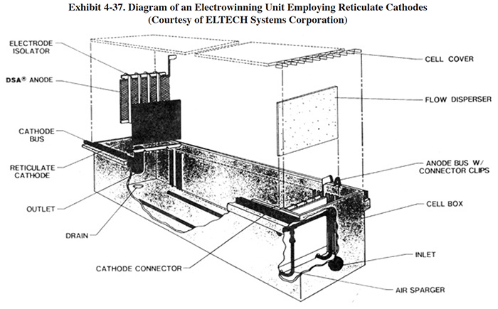
The metalized surface of the reticulate cathode is rough and therefore has a greater actual surface area than its geometric surface. The manufacturer indicates that the surface area is 10 times greater than the apparent area. The higher surface area permits use of the units at lower metal concentrations than possible with conventional flat plate cathodes of the same size. One user of this technology (PS 196) indicated that it treats cadmium to below 5 mg/l, but that a significant concentration of residual cyanide remains. A diagram of a reticulate cathode electrowinning system used by nine survey respondents is shown in Exhibit 4-37.
 |
The wire mesh and expanded metal types are used as anodes in a plating bath after they have been plated with metal in the electrowinning unit (ref. 130). The reticulate cathodes are not reusable. When they are fully coated with metal, they are either sent off-site for sale as scrap or are discarded, depending on the type and purity of the deposit and the ability of a reclaim site to deal with the non-metallic core of the cathode. Operations where the cathodes are discarded are referred to as extractive methods of electrowinning (ref. 421).
 |
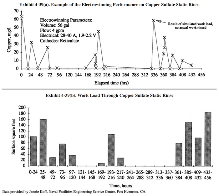 |
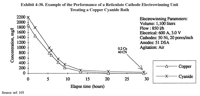
Vendor provided data for the electrowinning treatment of a copper cyanide bath using a reticulate cathode design is shown in Exhibit 4-38. Operating data for a reticulate cathode unit provided by the Naval Facilities Engineering Service Center (Port Hueneme, CA) are graphically displayed in Exhibit 4-39. These tests were performed on a printed circuit board line over a time period of 432 hours (18 days). The electrowinning unit is a Retec Model 6 (21 ft2 of reticulate cathode surface area). Exhibit 4-39 (a) shows the copper concentration in the dragout rinse tank (56 gal) during the test period (same set-up as EW configuration EW-1a, Exhibit 4-32). The highest concentration measured in the dragout rinse during the test was 64 mg/l Cu. The copper concentration invariably fell to less than 1 mg/l overnight and during any idle period of a few hours duration. During one segment of the test, the copper concentration fell from 16 mg/l to 1.5 mg/l in 2 hours; during another segment, the copper concentration fell from 25.7 mg/l to less then 1 mg/l in 5 hours. The data suggest that for the conditions present at this facility, the copper concentrations will generally remain below 60 mg/l in the dragout rinse and will reach 1 mg/l or less within approximately 5 hours or less after plating has ceased.
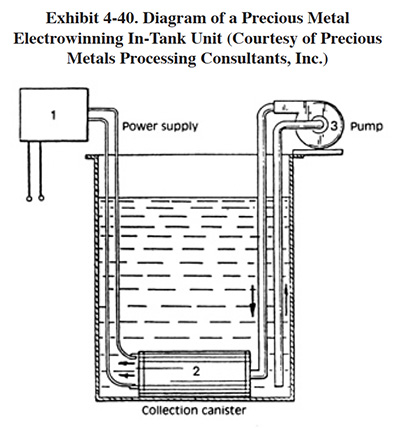 |
A reticulate and disposable cathode is often used for gold electrowinning. A small commercial unit, operating with only 25 amps output, is shown in Exhibit 4-40. The cathode of this unit is placed directly into a small dragout tank. This unit is applicable to the recovery of most precious metals. It was used by four respondents to the Users Survey. The metal deposited onto the cathode is recovered chemically and/or thermally (dissolved in acid from cathode, precipitated, then melted or simply melted from the cathode) (ref. Gold Bug File).
4.5.4.4 High Surface Area Cathode Units
High surface area units are used in rinsing operations, where low concentrations of metals are desired. The advantage of maintaining a lower equilibrium concentration is two fold; first, the percentage of material recovered is increased and second, the free rinse after the recovery rinse may be sufficiently dilute to be sewered without treatment. High surface area units extract the metal onto cathodes made of fibrous material such as carbon. The high surface area allows for metal removal at solution concentrations much lower than flat plate cathode types and even the reticulate types. The fiber cathode is regenerated by passage of a strip solution through the unit and reversal of the current. Plating solutions can sometimes be used as the strip solution and returned to the bath for reuse. More commonly, the concentrated metals in the strip solution are removed by a second electrolytic unit, employing conventional electrowinning.
One commercially available carbon-fiber cathode system employs a three dimensional flow-through type assembly, consisting of carbon fibers woven into layers of fabric secured to the electrical distribution feeder sheets in a plastic coated frame (ref. 128 and Baker Brothers file).
The high surface area units have been mostly applied to recovery of metals from the rinses of cyanide based plating processes (e.g., cadmium, copper, zinc, gold and silver). These units remove metal ions to low concentrations and also oxidize the cyanide in the rinse water. Other applications noted in the literature include: copper etch, electroless copper, acid gold, acid silver, tin-lead fluoborate and tin-lead sulfate solutions.
Cyanide oxidation with HSA units can be performed with the addition of sodium chloride electrolyte to the rinse, although the practicality of the process is not widely accepted. With this method, the chloride ions are oxidized to chlorine at the anode and react with cyanide in the rinse (ref. 39).
4.5.4.5 Other Equipment/Operational Considerations
Various design methods are used in commercial equipment to achieve agitation and reduce the impact of concentration polarization. One manufacturer (ref. Eco-Tec file) advertises the use of convection air agitation that directs a uniform curtain of fine air bubbles across the face of the cathode and thereby bringing a constant supply of fresh solution to the cathode surface. According to the manufacturer, the improved agitation permits close anode to cathode spacing (1 in.) which reduces the IR (ohmic) resistive voltage drop across the cell, resulting in lower energy consumption. It also reduces the overall size of the electrowinning unit for a given cathode area requirement. Another manufacturer uses a fluidized bed design to achieve agitation (ref. BEWT file). With this design, mesh metal electrodes sit in a bed of inert glass beads, which is fluidized by the action of the pumped electrolyte. The scouring action of the beads against the mesh electrodes unit provides agitation to reduce concentration polarization and improves the quality of the deposit. Due to the mesh design, the deposit cannot be mechanically removed from the cathodes. Rather they are placed into specially designed anode bags and put into plating tanks, where they function as anodes. This equipment is advertised for recovery of nickel, nickel-iron, zinc, cadmium, silver and gold. Most of the electrowinning units manufactured for silver recovery for use in the photographic industry employ a rotating cylindrical cathode. Rotating the cathode provides the needed agitation at the interface between the cathode and the solution.
Several types of controls are available with electrowinning units. Inexpensive units usually have just an on/off switch as the only means of current control. Such equipment may be satisfactory if the solution variables remain relatively constant. Many units have variable current control and a meter to indicate current flow in the solution. Sensor probes are available on some units which will automatically adjust the current to the metal concentration. Microprocessor controls are also offered by many manufacturers.
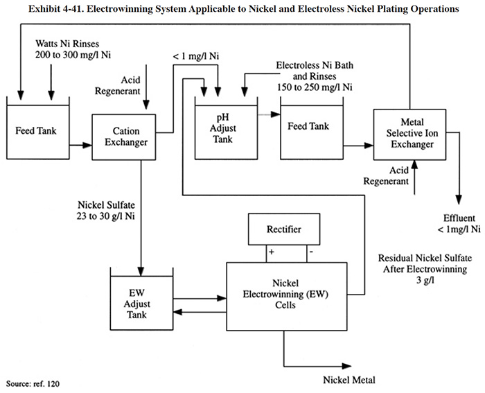 |
Nickel, although it is one of the most frequently plated metals, has traditionally not been recovered by electrowinning. This is partially due to the fact that alternative technologies exist for nickel recovery, but is also due to the difficulty of the nickel electrowinning process. The recovery of nickel using electrowinning has become more common in recent years owing to research and development. The reason for the difficulty with nickel is that the pH of the electrolyte (typically a sulfate media) will drop as the electrowinning process proceeds due to the electrode reaction (electrolysis) that produces hydrogen ions. As this occurs, the metal deposition rate will decrease and hydrogen production will continue to increase. For this reason, it is necessary to control the pH of the electrolyte. A nickel recovery system employing ion exchange and electrowinning is shown in Exhibit 4-41. With this process, the electrolyte is continuously circulating from the cell to an adjustment tank where the critical operating parameters are controlled. This includes caustic addition for pH control. Another reference suggests the use of ammonia for adjusting the pH of Watts, Woods and sulfamate nickel baths. Note that the overall recovery system in Exhibit 4-41 includes the recovery of metal from both electroplating and electroless plating processes. A selective ion exchange column is used prior to electrowinning to separate the nickel from the chelates contained in the electroless bath and rinses.
 |
4.5.5 Costs
 |
4.5.5.1 Capital Costs
The capacity requirement for conventional electrowinning depends most heavily on the amount of metal to be recovered and the rate of metal deposition. Factors that influence the rate of metal deposition are (ref. 39 and 128):
- Electrode type and area
- Agitation rate (or in general, mass transfer)
- Solution chemistry
- Electrical variables
- Temperature
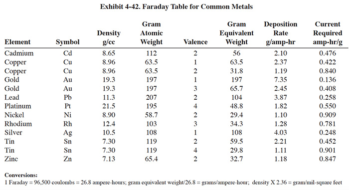
The cathode surface area depends on the size and number of the cathodes employed in the unit. The agitation rate, average metal concentration in the rinse solution, solution conductivity and temperature all influence the current density that can be maintained and still result in an even, homogeneous metal deposit on the cathode. The higher the current density allowed, the higher the rate of metal deposition per unit area of cathode (ref. 39). Exhibits 4-42 and 4-43 present useful data for cathode sizing exercises.
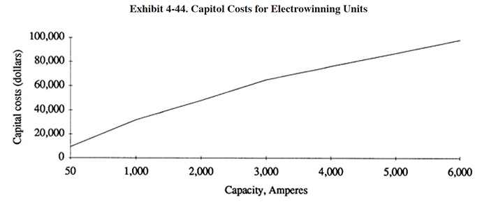
A nearly linear relationship between cost and capacity is displayed in Exhibit 4-44. Capital costs, therefore, can be estimated once capacity requirements are determined. Most vendors refer to capacity in terms of amperage; more precisely, the maximum amperage setting on a unit's rectifier. Less commonly, capacity is expressed in terms of total cathode area. The rectifier and electrodes comprise the majority of the cost for most units; other contributing components are the fluid containment tank, pumps, filters and optional metering devices.
The strategy for determining the appropriate capacity of an electrowinning unit for a specific application is straightforward in theory: match the expected plate-out rate of the unit with the application's waste metal generation rate. For dragout tank applications, such as those diagrammed in Exhibit 4-32, the rate at which metal is introduced into the tank is determined either by direct analysis, or by a method such as that proposed in Section 3.5.3.1. The plating rate of the metallic species in question is obtained from the Faraday Table presented in Exhibit 4-42. Capacity requirement in amperes, therefore, is the introduction rate in g/hr divided by the plating rate in g/amp-hr. This quotient requires an adjustment for expected current efficiency (that portion of current available to the cell that actually is employed reducing the target metal on the cathode) before serving as a reliable guide for required capacity. Current efficiency for electrolytes with high metallic concentrations will approach theoretical levels, but it may range down below < 10% of the theoretical rate for electrolytes concentrations of metal below 100 mg/l.
 |
Other application configurations lend themselves to similar analysis. For units employed to electrowin metal from ion-exchange regenerant, the volume and concentration of the regenerant is required for capacity sizing. These quantities will be known from the analyses required for ion exchange sizing. The time available for electrowinning is limited by the time between regenerations. Spent regenerant may be contaminated by several species of metallic ions; this will make the calculation of appropriate cell amperage less accurate. For batch dumps, concentration of metal in the spent bath and the dump period are usually available data. The following formula applies to regenerant or process batches alike.
amps = [g/batch]/[g/amp-hr]/[hours/batch or cycle]
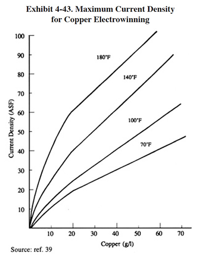
Cell amperage is not likely to approach the maximum rectifier output. It is limited by the maximum practical cathode current density for the metallic species being electrowinned which, in turn, is a function of metallic concentration. Thus, in practice, it is the total cathode area and the concentration of metal in the electrolyte that best determines the practical amperage capacity of a unit. Exhibit 4-43 demonstrates the considerable effect of concentration (and temperature) on maximum current density for copper electrowinning; similar curves are to be expected for other metals.
Low concentration electrolytes present significant sizing implications. Plating proceeds at a fraction of high concentration current densities and efficiency is lost as current is wasted reducing hydrogen at the cathodes. Units lacking design features aimed at reducing the thickness of the polarization depletion layer and not equipped with high surface area cathodes will be least efficient in these environments. At concentrations of <100 mg/l, a reasonable current efficiency estimate may be 10% or less. These factors must be offset with larger capacity units. Success at low concentrations will also depend on the metallic species being electrowinned, the presence of multi-valent cations in the electrolyte (such as tin and iron, which further lower efficiency by oxidizing to higher valence at the anode and reducing to lower valence at the cathode, thereby wasting current and yet staying in solution) and the time available for electrowinning (eventually, units so designed can reduce concentrations of certain metals to below compliance levels).
Anode and cathode construction will significantly impact the cost of an electrowinning unit. A list of cathode and anode materials is displayed in Exhibit 4-36. Materials options for a specific application are limited by the peculiarities of the electrolyte being electrowinned and by the manufacturer of the unit. Cost differences can be significant; e.g., ELTECH Systems Corporation offers it's units with either graphite or DSA® (proprietary rare earth coating) anodes. The graphite anodes were quoted in 1993 at $80, while the DSA were $335. For a Retec 25 (26 anodes) this represents a cost difference of $6,630.
 |
 |
4.5.5.2 Operating Costs
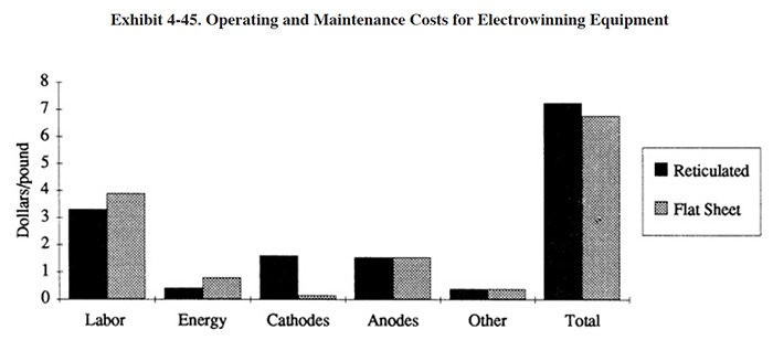
Typical operating costs for this technology are shown in Exhibit 4-45. Respondents employing this technology reported their annual operating costs to be only $4,100/yr on average, roughly split between the labor and non-labor categories. This technology is not labor-intensive nor expensive to run. Operating costs components are labor, electrode replacement, maintenance and energy.
Labor costs are largely installation- and application-specific. Units used in batch configurations may require considerable solution transport, pre-adjustment of the electrolyte, cleaning of salt deposits and adjustment of batch releases from the unit. On the other hand, dedicated dragout rinse units treating fluids with lower total dissolved solids may require only occasional cleaning and rare maintenance of any kind. In all, little scheduled maintenance beyond cleaning and replacement of corroded connectors is to be expected.
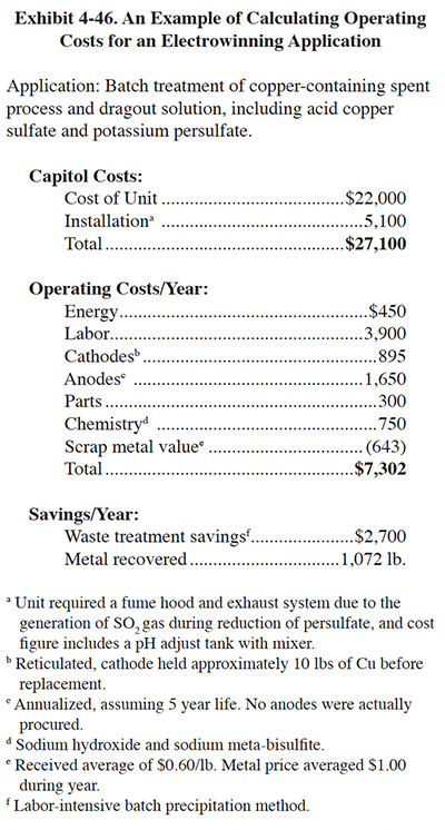
Energy costs will comprise only a small percentage of total operating costs for most applications. For large units, however, energy costs may more significant in relation to total operating costs as other expenses benefit from economies of scale. Predicting energy costs for a given application is complicated by the fact that several variables affecting total power consumption are difficult or impossible to know prior to actually running the unit. Conductivity, required voltage, rectifier efficiency, and current efficiency are either unknown or will vary with time or batch to batch. Once the unit is operating, energy costs will become easy to assess. In the example given in Exhibit 4-46, electrical costs were $0.4198/lb of Cu; these costs reflect metal removal to <5 mg/l and should be typical of similar applications.
Electrode replacement costs depend on their construction and life expectancy. Stainless steel cathodes are usually peeled or scraped free of plating deposits and reused. Reticulated cathodes must be replaced after they accumulate sufficient metal to lower their effectiveness, roughly 5-10 pounds/sq. ft. of cathode area. Anodes may, as in the case of DSA® and other proprietary materials, be semi-permanent and last in excess of 5 years. Graphite anodes are well-known to "melt" or gradually exfoliate carbon particles into the electrolyte; this obviously shortens their operating life.
The example offered in Exhibit 4-46 has total operating costs at $6.81/lb of Cu. Unlike a dragout rinse application, considerable labor was involved transporting and adjusting spent process baths prior to electrowinning. Labor, at $3.64/lb, was by far the largest operating cost component.
 |
4.5.6 Performance Experience
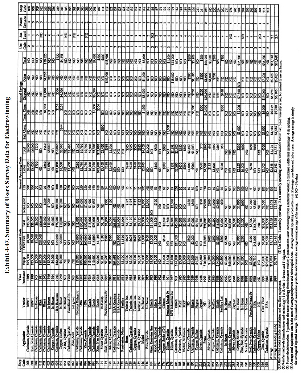
A partial summary of the User Survey data relative to electrowinning is presented in Exhibit 4-47. There are a number of general observations that can be made from these data and other data contained in the Users Survey database and literature:
- The average satisfaction level for the electrowinning technology is 3.1 (on a scale of 1 to 5, with 5 being most satisfactory), which is lower than the average level rating for all recovery technologies. Fifty-six percent of the shops indicated that this technology satisfied the need for which it was purchased and another 15% indicated that it partially satisfied the purchase need. The following is a breakdown of the reasons why shops purchased this technology:
To meet of help meet effluent regulations: 38 To reduce plating chemical purchases: 9 To reduce the quantity of waste shipped off-site: 20 To reduce wastewater treatment costs: 20 To improve product quantity: 1 Other (mostly to recovery valuable metals): 8
- The use of electrowinning for metal recovery generally did not impact production quality or the rate of production. The following responses were provided:
Product Quality Production Rate Improved 0 1 No Change 55 50 Decreased 1 5 (Where product or production impacts occurred, the respondents did not provide any details of the impacts.)
- Most plating shops indicated that based on their experience with this technology, if given the chance, they would purchase the same type of equipment from the same vendor. The following is a breakdown of their responses:
Purchase the same technology from the same vendor: 35 Purchase the same technology from a different vendor: 4 Purchase a different technology: 13 Do nothing: 4
- The major savings from the operation of electrowinning were reduced treatment chemical use, reduced sludge generation and the value of the recovered metal (especially precious metals and to a lesser extent, cadmium).
- Most of the respondents use electrowinning to recover metal from rinse water and incorporate dragout (or drag-in/dragout) tanks to concentrate the metals prior to electrowinning. The electrowinning system is either connected directly to the dragout tank or the dragout is periodically pumped to a side tank for electrowinning. Other configurations from the survey forms include: (1) an electrowinning unit recovered metal from a spray rinse (PS 184); (2) metal was recovered from a spent process solution (PS 039, PS 128, PS 164); (3) metal was recovered from a copper sulfate bath purge (i.e., used to control a buildup of metal concentration in bath) (PS 041).
- Nearly 50 percent of the respondents' applications of electrowinning were used for cadmium recovery.
- The most successful application of electrowinning appears to be precious metals recovery (based on the number of applications, the percentage of applications still in use, and the satisfaction level of the users). This includes the use of both commercial and home-made units. This is most likely due to the fact that noble metals are more easily recovered by electrowinning than common plated metals.
- All the HSA units purchased between 1979 and 1983 were purchased from a single manufacturer (HSA Reactors Ltd.). The average cost of these units was $66,360. The high capital cost was probably tolerated at the time because these units were advertised as compliance technologies rather than simple recovery methods (PS 276). As such, they were intended to fulfill a portion of a plant's conventional treatment requirements. These units received an average technology satisfaction level of 1.4. Asked what they would do if given the opportunity to repeat the technology selection process, the eight users of this technology indicated:
Purchase the same technology from the same vendor: 0 Purchase the same technology from a different vendor: 1 Purchase a different technology: 5 Do nothing: 2
Only one of these early HSA units is currently operating (PS 086) and that unit was extensively modified by the user by replacing the carbon cathodes with corrugated steel panels and by removing the heat exchanger and the cyanide destruct module. Some shops indicated that the performance of the HSA system was good, when it was operating (PS 012, PS 124, PS 276). Other shops reported complete dissatisfaction, e.g., "it has been a major expense and headache ... too much downtime" (PS 086). Another problem cited with this equipment was the competing nature of the cyanide destruction and metal removal processes. As reported by PS 039, the cyanide destruction process reduced the technology's ability to remove cadmium. PS 086 also cited this problem and reported that they abandoned this portion of the technology.
Of the various "black box" technologies utilized during the late 1970's and early 1980's, a period when plating shops were installing equipment to meet the new Federal effluent standards, the high surface area units probably had a negative impact on the utilization of advanced technology. Following this time period, the plating industry moved in the direction of conventional treatment with sludge dewatering and dehydration and off-site metals reclamation.
- Two HSA type units were purchased from a manufacturer other than HSA Reactors Ltd. in 1985 (PS 188). These are much lower cost units ($3,000) that are still in use and received higher than average satisfaction ratings.
- Eltech International Corporation, a producer of reticulated cathode units, manufactured more of the electrowinning units reported in the survey forms than any other manufacturer.
The average technology satisfaction level for these units was 2.9, slightly less than average. However, asked what they would do if given the opportunity to repeat the technology selection process, the users of this technology indicated:
Purchase the same technology from the same vendor: 8 Purchase the same technology from a different vendor: 0 Purchase a different technology: 1 Do nothing: 0
- Some performance failures of the electrowinning technology can be attributed to misapplications by the user. This is especially true with the use of home-made units and units purchased from manufacturers' representatives rather than the manufacturer. For example, PS 128 purchased an electrowinning unit from a manufacturer's representative to recover copper, nickel and chromium (chromium cannot be recovered using electrowinning because very high concentrations of chromium are required for a deposit to form) from a spent nitric acid solution (inappropriate electrolyte). The user indicated that he intended to recover the metals and reuse the nitric acid. The supplier-stated capacity of the unit, according to the user, was 8 gpm (flow-through is an inappropriate application). The result was that "it did not work" and "it fumed." Another shop (PS 146) that modified an old commercial unit indicated that they could not determine the proper electrical settings for its use. They were using the unit with a 5 gpm flow-through of zinc cyanide rinse water (flow-through is an inappropriate application because it does not permit sufficient time for the metal to be plated-out). That same shop indicated in their survey form that they are planning to use their electrowinning unit in the future for chromium recovery.
- Approximately 26% of the electrowinning units used by respondents were constructed in-house (where the manufacturer was not given, those data were not used in the percentage calculation). These units received a higher average satisfaction level than the commercial units (3.6 vs 3.1), although plating shops with home-made electrowinning units gave mixed performance reviews. The capacity and quality of the components that went into these units probably had a significant bearing on performance. Also, the lack of technical support available led to misapplications and unsolvable problems. For example, PS 025 spent $ 15,000 on their equipment in 1986. This unit was still running at the time of the survey (1993) and the shop gave the unit a satisfaction level of 4. On the other hand, PS 036 constructed a unit in 1984 using components available in-house and purchased iridium coated anodes ($4,000) from an anode supplier. The unit had a 60 to 70 percent downtime, reportedly was labor-intensive and their efforts were abandoned in four months. This unit was applied to treatment of dragout and spent bath (copper cyanide). PS 041 constructed a unit for $4,000 in 1990. Although this unit is still operating, it has a downtime of 20% and is ineffective in removing copper unless the copper sulfate concentration is 75 g/l or higher (unit used to treat bath purge, lower copper concentration and electrowinning discharge is returned to bath). PS 043 abandoned their home-made unit because of problems with conductivity and sluffing off of metal (zinc) from the cathode.
4.5.7 Operational and Maintenance Experience
The following summarizes the respondents O&M experiences and provides operating labor information.
- The average number of annual operating hours per electrowinning unit were: 140 hrs/yr. The labor categories commonly used for operating this technology are wastewater treatment plant operator and trained technician. The following is a breakdown of the responses for skill requirements (based on data from 39 respondents):
Environmental Engineer: 4 Process/Chemical Engineer: 5 Chemist: 12 Consultant: 2 Plumber/Pipe Fitter: 13 Electrician: 11 Vendor: 3 Senior Level Plater: 10 Junior Level Plater: 14 Wastewater Treatment Plant Operator: 20 Trained Technician: 17 Common Labor: 10
- The average percentage of downtime for this technology experienced by the respondents was 20 percent.
- The most frequent and significant operational and maintenance problems identified with electrowinning include: labor intensive to clean (e.g., anode cleaning, electrode contact cleaning) (PS 025, PS 053,); high level of fuming or gassing (PS 036, PS 053, PS 128); sluffing off of deposit from cathode (PS 043); temperature build-up (PS 036); salting of the electrolyte (PS 036); anodes polarize at high current density and deteriorate or are attacked by chemicals (PS 213); anodes passivate (PS 239); and deterioration of fiber cathodes (PS 086).
- Approximately 40% of the total number of electrowinning units reported in the survey forms are no longer in use.
- Some shops reported that poor support from the manufacturer was partially the cause of their system failure. PS 008 indicated that their zinc recovery unit was removed after 4 to 5 months of operation because they could not get help with system problems ("everything went wrong ... like pulling teeth to get help").
- Two of the shops that purchased equipment from HSA Reactors Ltd. indicated that the fact the company went out of business led to the failure of their systems (PS 012, PS 276). The carbon cathodes and other equipment components used in their products were too unique to find elsewhere. Also, users cited numerous mechanical problems (e.g., pump failures-PS 086) with these units and they complained about the fragile nature, short life and high cost of electrodes (PS 039, PS 086). The labor costs for HSA systems appear to be higher than the average electrowinning system, which points to the complexity of the systems. Further, the operation of the equipment required a moderate level of expertise. As one shop (PS 276) indicated, it was "too technical for our people." Generally, it is observed that this technology was probably sound from a theoretical standpoint, but lacked good engineering design and components. A similar conclusion is presented in a report sponsored by the Canadian Branch of the AESF (ref. 351). That report concluded that such a system could be operated in a manual mode, but that more developmental work was needed before an adequate automated system could be marketed.
- Some facilities have added sodium chloride to the electrolyte to increase the efficiency of cyanide destruction (PS 036). One shop reported unsatisfactory results, because the solution temperature increased and gassing occurred and the residual cyanide level was too high for sewering (PS 036).
- Shops that reported difficulty with the electrowinning process cited two possible technical causes, including: (1) contamination in electrolyte (PS 036, PS 090) and (2) build-up of carbonates (PS 036).
- Shops using the small precious metals recovery units (both commercial and in-house) reported none or very few operational and maintenance problems.
4.5.8 Residuals Generation
The standard flat plate cathode unit recovers metals in the form of metal sheets 1/8 to 3/8 inch thick. Some shops (e.g., PS 053) described their deposit as a metal sponge rather than a metal sheet. Depending on the purity of the deposit, which in turn will depend on the purity of the solution being recovered, these residuals can be either used as anodes, sold to a scrap dealer or refiner for recycle, or disposed of in a landfill. When sold as scrap, the plater receives approximately 50 to 90% of the commodity price for the material, depending mostly on quantity and purity. Some electrowinning cathodes are specifically designed to be hung in plating tanks after they are coated with metal and serve as anodes. This eliminates the need to mechanically remove the deposit.
The reticulate cathodes cannot be used as anodes. They must be either sent off-site for recovery or disposed of. Most of the shops responding to the survey that use reticulate cathodes send them to a scrap dealer. They receive approximately the same price as for flat plate cathode material.
The high surface area electrolytic units generate a strip solution that can be recycled to a plating bath, or more frequently, is recovered using conventional flat plate electrowinning.
4.6 ELECTRODIALYSIS
4.6.1 Overview
The electrodialysis technology employs ion-permeable and selective membranes under an applied d.c. potential difference to separate ionic species from an aqueous solution. Its primary application for chemical recovery is nickel plating, where it competes with recovery rinsing (dragout tanks), evaporation technologies and ion exchange. As such, it has not seen widespread use, despite being commercialized for this application for nearly fifteen years.
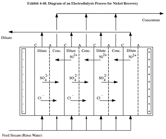 |
When used for nickel recovery, a concentrated rinse solution is pumped into an electrodialysis unit that is comprised of a stack of alternating cation- and anion-selective membranes, each separated by a spacer through which the solutions are allowed to flow (Exhibit 4-48). Due to the electrical potential applied across the stack, cations (Ni2+) in solution migrate toward the cathode, and anions (SO42- and Cl-) toward the anode. When a cation encounters a cation-selective membrane, it passes through. As it continues to migrate, it will subsequently encounter an anion-selective membrane through which it cannot pass and will remain in that compartment. Similarly anions migrate toward the anode, pass through anion selective membranes and their travel is halted when they encounter a cation-selective membrane. This process results in alternating compartments between consecutive membranes becoming increasingly enriched (concentrate) and increasingly depleted (diluate) in ion concentration (ref. 399). Based on data presented in the literature, the feed stream (typically from a dragout tank) usually contains 2 to 5 g/l Ni, the concentrated return stream contains 30 to 60 g/l Ni and the depleted stream contains less than 200 mg/l Ni (ref. 32). The return stream is less concentrated than the bath (typically 70 to 90 g/l Ni). However, surface evaporation from the plating bath tank is generally sufficient to volumetrically accommodate complete assimilation. The percentage of nickel recovered from the feed stream is typically 90 to 95%.
A potential advantage of electrodialysis over other concentrating and return methods of nickel recovery (e.g., evaporation and reverse osmosis) is its ability to selectively retard the recovery of certain organic materials that tends to buildup in nickel plating baths, while more freely permitting the transport of a desirable organic bath constituent (saccharin) and nickel salts. This aspect of the process could reduce the frequency of bath purification as compared to other recovery schemes. Bath purification causes the loss of 10 to 15% of the bath per cycle, which significantly reduces the pollution prevention benefits of recovery (ref. 28).
4.6.2 Development and Commercialization
Although the phenomenon of electrodialysis was observed in the 1800's, it did not achieve any commercial application until durable, ion-selective membranes were developed in the 1950's (ref. 39). The two early applications of this technology, desalination and recovery of edible salt from sea water, still constitute the bulk of membrane utilization. The largest electrodialysis installations are salt recovery systems located in Japan. These systems replaced solar ponds that once occupied large tracts of land (ref. 400).
Large-scale industrial usage of electrodialysis began in the early 1970's with applications in chemical processing, biotechnology and water pollution control. In 1972, the first attempts were made to use electrodialysis to reclaim plating chemicals from rinse solutions (ref. 32). This early work was performed with unidirectional systems, where the transfer of ions is in one direction only. These efforts were plagued by membrane fouling with scale, slime and undesirable organics (ref. 32). Subsequently, the electrodialysis reversal (EDR) process was utilized, where there is a periodic reversal of direct current flow through the membrane stack and a simultaneous interchange of diluting and concentrating streams. This improvement greatly reduced the occurrence of membrane fouling. By 1984, there were more than 100 recovery units operating in the U.S. on a variety of plating solutions. The major area of application was nickel plating, with most other applications restricted to cyanide baths (e.g., gold, cadmium, silver and zinc). Additional applications at that time, mentioned in the literature, include tin and tin-lead fluoroborate and trivalent chromium (ref. 39). Since approximately 1985, there have not been any major changes to electrodialysis as applied to chemical recovery from rinse waters. However, similar technology applications for bath maintenance have significantly increased. Presently, membrane electrolysis, a related technology, is applied to the maintenance and reformulation of solutions containing chromic acid, nitric acid, sulfuric acid or sodium hydroxide (Section 5).
4.6.3 Applications and Restrictions
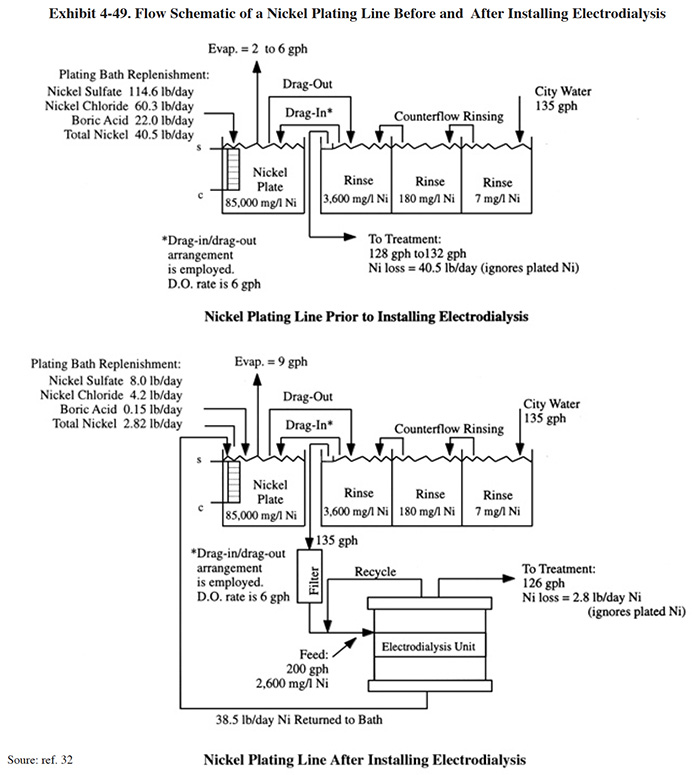
The application of electrodialysis for recovery of nickel plating chemicals is shown in Exhibit 4-49. This application, which includes a material balance, was taken from the literature (ref. 32), and is based on an actual case study performed by an electrodialysis equipment manufacturer. The work for this application was performed at a job shop with an automatic nickel barrel plating operation. The plating and rinsing configuration used prior to the implementation of electrodialysis is also shown. Based on a comparison of the two diagrams, the electrodialysis system recovered approximately 38 lbs of nickel per day more than the existing dragout/drag-in recovery rinsing system. The difference in plating tank evaporation rates between the original and revised systems was not discussed in the article, but presumably was due to a change in the operating temperature of the bath.
 |
Most applications for this technology have involved nickel recovery including Watts, sulfamate and bright nickel plating solutions and nickel galvanizing. Other applications identified by vendors include: gold, copper, cadmium, platinum, silver and zinc cyanide; tin-lead, palladium, zinc phosphating and zinc galvanizing (ref. 134, Kinetic Recovery Corporation file, Graver Co. file).
4.6.4 Technology/Equipment Description
This subsection contains names of commercially available electrodialysis equipment that is manufactured and/or sold by vendor survey respondents. This is intended to provide the reader with information and data on a cross section of available equipment. Mention of trade names or commercial products is not intended to constitute endorsement for use.
Graver Water, a division of The Graver Company, markets electrodialysis units manufactured by Tokuyama Soda, a world leader in the membrane technology. Their target industries are food, photograph finishing, pulp processing, waste control and metal finishing. Their key metal finishing applications include nickel and zinc recovery from galvanizing and acid or alkali recovery.
Kinetic Recovery Corporation markets electrodialysis equipment for various applications, including: Watts nickel, copper cyanide, cadmium cyanide, and zinc phosphates. Their typical units have membrane surface areas ranging from approximately 35 ft2 to 190 ft2, although all units are custom designed to meet individual process needs. Their systems are skid mounted and include: membrane stack, holding tank for concentrate, holding tank for diluate, holding tank for electrode rinse, three sets of level controls, three pumps for liquid transfer, plumbing, automated valves, flow meter, pressure gauges, cartridge filters and control panel.
4.6.5 Costs
4.6.5.1 Capital Costs
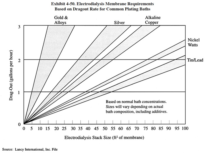
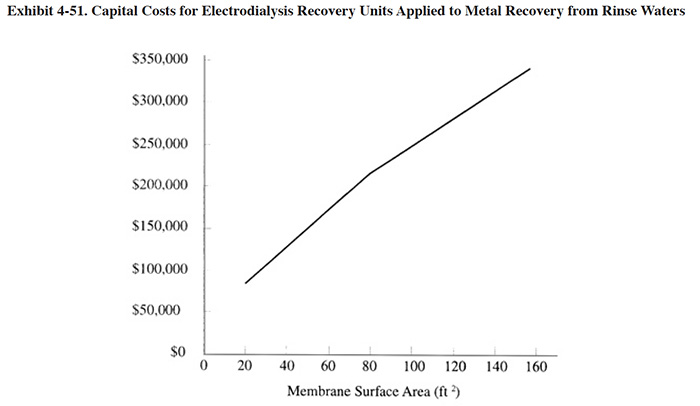
The capital cost of an electrodialysis unit is related primarily to the stack size, which can be expressed in terms of membrane area. Exhibit 4-50 shows typical membrane area requirements for Watts nickel solution and other applications in terms of the dragout rate (gph). Exhibit 4-51 shows capital costs, based on feed stream flow rate (typical feed stream concentration of 2 to 5 g/l dissolved metal.
 |
 |
4.6.5.2 Operating Costs
Electrodialysis operating costs include O&M labor, electricity and replacement costs for membranes. Estimated operating costs are 15 to 30 percent of investment costs.
 |
4.6.6 Performance Experience
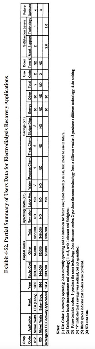
Only two of the user survey respondents indicated that they have used electrodialysis as a recovery technology (PS 012 and PS 125). PS 012 purchased a system from LEA in 1982 and PS 125 purchased a system from Baker Brothers in 1986. A summary of the data provided by these respondents is shown in Exhibit 4-52. Neither of these applications was successful. Failure of the technology at PS 012 was attributed to maintenance problems with the membrane and associated repair and parts replacement costs. Their system was removed from service in 1987 after 5 years of service (non-continuous due to O&M problems). They indicated that the technology did not satisfy the purpose for which they purchased it (i.e., to help meet effluent regulations and reduce operating costs). PS 125 did not provide many details on their system's performance. They simply stated: "machine returned after threatened law suit because it never worked." Presently PS 125 uses a vacuum evaporator for nickel recovery that has been relatively successful (only reported problem was a build-up of sodium chloride in the nickel bath, see Section 4.3).
4.6.7 Operational and Maintenance Problems
Only one of the two survey respondents who used this technology provided any information on O&M problems. PS 012 provided the following statement:
"Lack of availability of replacement membranes and long repair time by factory after membrane failure (1 year and up to 6 months down) coupled with high repair cost for each failure ($6,000) made this a non-viable technology, was abandoned circa 1987."
As with most membrane technologies, the life span of the membrane is a key concern to the system owner. One vendor provided estimates of membrane life span during the Vendors Survey. Kinetic Recovery Corporation estimated that their membranes (OS-FD/FS types) last three to seven years for all recovery applications. The Graver Company provided the following estimates for membranes, gaskets and electrodes for acid and alkali recovery (i.e., from concentrated baths, not rinse water).
Acid Recovery Alkali Recovery Membranes 0.5 to 1.0 year 0.3 to 1.0 year Gaskets 1 to 2 years 1 to 2 years Electrodes 2 to 4 years 2 to 4 years
The Graver Company further indicated that the longevity of membrane life was dependent largely on the level of contaminants present.
4.6.8 Residuals Generation
When applied as a chemical recovery technology to plating rinse waters, electrodialysis produces two effluents from the unit: a concentrated stream that is recycled to the bath and a dilute stream that is either reused as rinse water or discharged to treatment.
Typically, electrodialysis recovers up to 95% of the plating chemicals in the dragout. The remaining 5% are lost when discharged from the rinsing system or directly from the recovery unit. This waste is typically treated on-site which generates a hazardous sludge (RCRA hazardous waste code F006).
Other miscellaneous wastes generated by this technology include spent pre-filtration cartridge filters and worn or damaged modules, electrodes and gaskets. No quantitative data were available for these other wastes.
4.7 REVERSE OSMOSIS
4.7.1 Overview
Reverse osmosis (RO) is a separation process that has been employed in the metal finishing industry to purify raw water (e.g., city water) before use as rinse water, recover plating chemicals from rinse water, and polish wastewater treatment effluents (usually for reuse as rinse water). Of particular interest in this section of the report is the application of RO for chemical recovery, however; end-of-pipe applications are also covered. Use of this technology as a raw water treatment technology is not covered in this report.
As a recovery technology, RO has been applied to a range of processes, including: brass, chromium, copper, nickel, tin and zinc plating solutions (ref. 269, 348), with nickel recovery being the most frequent and successful (ref. 39). Of the 318 plating shops responding to the Users Survey, only six applications of RO chemical recovery were identified. The survey also included one application for end-of-pipe treatment and several applications of raw water purification. The infrequent use of RO for chemical recovery may be due to the limited number of baths to which it has been successfully applied and the availability of competing technologies (especially for nickel plating). Further, one of the competing technologies frequently used for nickel recovery is atmospheric evaporation, which has a very low capital cost.
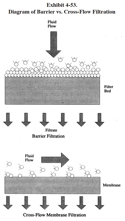
Reverse osmosis is often referred to as a "crossflow filtration" process. This term, which also describes most ultrafiltration and microfiltration equipment used by the metal finishing industry, distinguishes these processes from surface barrier filtration, which operates in dead-end flow. As shown in Exhibit 4-53, in dead-end filtration, all of the feed solution is forced through the membrane by an applied pressure. With crossflow filtration, the fluid to be filtered is pumped across the membrane, parallel to its surface. Because the feed and concentrate of RO flows parallel to the membrane instead of perpendicular to it (i.e., dead-end flow), the process is termed crossflow. The pressure required to drive the process is determined by the specific nature of the feed solution and the membrane pore size (ref. 380, Osmonics file).
 |
There are several key differences between RO and ultrafiltration/microfiltration: (1) only RO has the ability to concentrate dissolved salts (e.g., plating chemicals); (2) RO cannot tolerate significant concentrations of suspended solids, whereas the other two processes can, especially microfiltration; and (3) RO operates at higher pressures and usually requires a heavy gauge stainless steel housing, whereas the other two lower pressure processes can be housed in plastic or lightweight stainless steel. It should be noted, that whereas RO is a distinctly unique filtration process, ultrafiltration and microfiltration are similar to one another and have overlapping definitions (ref. 380). Microfiltration, which has the largest pore size of the three technologies, is discussed in Section 5, as a method of alkaline cleaner maintenance. Also, both microfiltration and ultrafiltration are discussed in Section 7, as end-of-pipe polishing technologies. Ultrafiltration is also used by several survey respondents for the recovery of electrocoat (paint), an application not covered by this project. It is also used in the machining industry for the recovery of cutting oils.
RO theory is based on two physical processes: osmosis and ionic repulsion. Osmosis is related to diffusion, which describes the tendency of molecules in solution to move about until they are uniformly distributed. Osmosis is the tendency for diffusion to take place across a semipermeable membrane. It occurs when a water permeable membrane separates two solutions of different concentrations of dissolved solids. Pure water will flow into the concentrated solution until an equilibrium energy state is achieved. By applying pressure to the more concentrated solution, the normal osmotic flow is reversed and pure water is forced through the semipermeable membrane into the less concentrated solution.
Suspended solids are blocked by mechanical exclusion and dissolved solids are chemically repulsed by the membrane surface. Multi-charged ions are rejected at rates exceeding 99 percent and single-charged ions have rejection rates in the range of 90 to 96 percent. RO will also reject neutral solutes, although no general efficiency data are available. Besides ionic charge, rejection efficiency is also affected by the concentration gradient. As the concentration gradient increases, the rejection efficiency decreases. The flow of water through an RO membrane (flux) is determined by the pressure differential across the membrane. Higher pressure differentials generally result in higher flow rates.
The RO process is designed to operate continuously. The RO membrane is enclosed in a pressure vessel and the feed stream is pumped through the vessel under pressure, 400 to 1,000 psig, where it is separated into a clean water permeate stream and a concentrated chemical stream by selective permeation. Three important parameters describe the performance of the RO process: recovery, flux, and rejection.
Recovery is defined as the percentage of the feed that is converted to permeate and it is usually expressed as percent. Flux is the rate at which the permeate passes through the membrane per unit of membrane surface area. Rejection is the ability of the membrane to restrict the passage of dissolved salts into the permeate, and is related to particular salt species (ref. 39).
There are different types of RO membranes used (tubular, spiral wound and hollow fiber), the selection of which depends mostly on the applications and in particular the plating bath chemistry. The most common RO membranes are the hollow fiber and spiral wound configurations.
Most reverse osmosis systems are designed with a single filtration stage operating below 700 psig. With a single stage system operating in this pressure range, the practical limit for concentrating plating chemicals in rinse waters is 15 to 20 g/l. Because this concentration is below that of most plating baths, a "solution volume" problem is sometimes created with an RO recovery application, in that there is insufficient head-room in the process tank for the return of the recovered chemical solution. This problem occurs especially with ambient to low temperature baths, where the surface evaporation rate is low. This condition limits the direct reuse of the RO concentrate stream in the plating tank. An evaporator can be used to further concentrate the solution or to supplement tank surface evaporation. However, the added capital and operating costs of an evaporator often make this approach less attractive than using an alternative recovery method.
Newer reverse osmosis technology includes multiple stage systems and higher operating pressures (800 to 1,000 psig). With the multiple stage design, the concentrate stream from the first stage is passed through a second stage to further concentrate the chemicals. This permits the direct reuse of some solutions that could not be directly recovered with the less effective single pass units.
The key attributes of RO as a recovery technology are: (1) it is an ambient temperature, low energy process; (2) it generates a permeate stream that is usually of sufficient quality that it can be reused for rinse water; and (3) for some applications, it has relatively low capital and operating costs as compared to other recovery technologies. The negative aspects of this technology are: (1) RO membranes can be fouled by precipitation products and/or suspended solids; (2) membranes have a fairly limited life-span; (3) this technology does not sufficiently concentrate the chemicals for direct return in some applications; and (4) similar to most other recovery technologies, RO returns both essential plating chemicals and unwanted impurities to the bath, unless some post-treatment is performed.
4.7.2 Development and Commercialization
Reverse osmosis is a relatively mature technology, having the distinction of being the first membrane-based separation technology to be widely commercialized (ref. 380). Much of the early developmental work for this technology took place in the late 1950's and the 1960's and focused on desalination for drinking water supplies. This work was sponsored by the U.S. Department of the Interior, Office of Saline Water (ref. 380). The spiral-wound element, which is the building block of modern recovery units was developed in 1963 (ref. 380). The first large industrial application of RO occurred in 1970 when a 100,000 gpd system was placed into operation at Texas Instruments' (TI) electronic manufacturing facility in Dallas, TX. The application at TI was the purification of municipal water for use in manufacturing. Now, essentially all electronics plants in the U.S. use RO for this purpose (ref. 65). The first RO metal finishing application for chemical recovery that was identified in the literature occurred in 1974, which was applied to copper cyanide (ref. 382). Other applications during the 1970's and 1980's included: bright nickel, Watts nickel, acid copper, acid zinc, and end-of-pipe effluent polishing. In 1976 the USEPA sponsored a series of experiments to evaluate the application of RO to plating chemical recovery. These experiments evaluated the performance and life-spans of membranes that were commercially available at the time (ref. 382).
Metal finishing applications of RO are very limited in comparison to those of desalination and other industrial applications. Worldwide, there are approximately 1,500 RO desalinating plants with a total capacity of more than 750 million gallons per day. Estimated RO membrane sales were approximately $118 million in 1988. Of these sales, Osmonics, one of the largest U.S. manufacturer's of RO equipment for the plating industry, accounted for $3 million (ref. 380). Osmonic's sales figures include not only the metal finishing industry applications, but also a range of other industries, including: food, beverage, dairy, chemical processing, and textile manufacturing. There are approximately 20 companies that manufacture and/or sell RO and ultrafiltration equipment to the U.S. plating industry (ref. 421). Of these companies, five responded to the NCMS vendors survey, but only four provided data on the number of systems they have sold within the metal finishing industry. The total number of systems sold by these four companies is 15, with nine units applied to chemical recovery, five applied to reuse of wastewater and one applied to raw water treatment. These numbers significantly understate the total number of RO units in use in the metal finishing industry because two major manufacturers (Osmonics and Ionics) did not provide data.
4.7.3 Applications and Restrictions
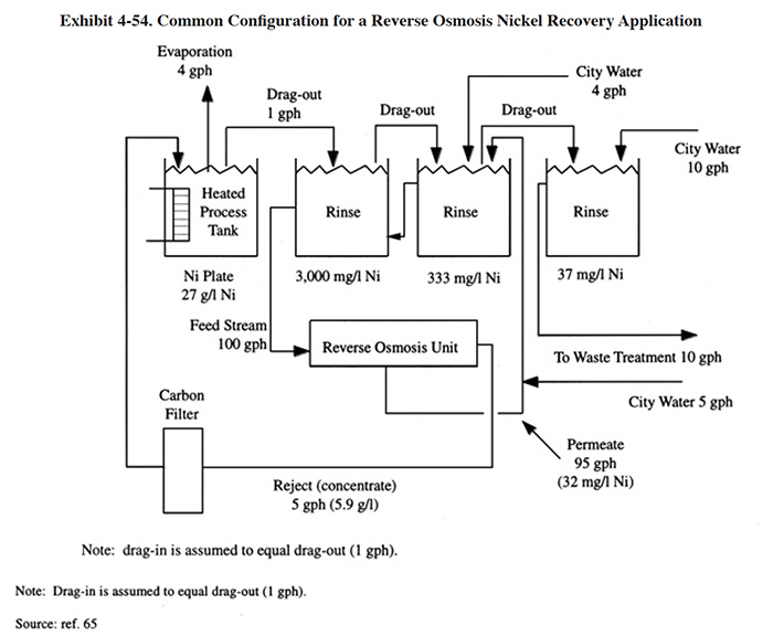
Exhibit 4-54 shows an example of applying reverse osmosis as a chemical recovery technology. In this example, nickel salts are recovered from rinse water and returned to the bath. A three stage counterflow rinse system is used in order to concentrate and reduce the flow rate of the feed to the RO unit. The 100 gph feed rate is typical for this application. The feed is pumped (high pressure feed pump) through a cartridge filter (typically 5 micron) and through the RO system. The reject passes through a carbon filter to remove bath impurities and is returned to the plating bath. In this example, the surface evaporation of the bath is sufficient to create the necessary head-room. The permeate is returned to the counterflow rinse system.
 |
The primary plating chemical recovery application for RO is nickel plating. This includes Watts nickel and bright nickel plating (ref. 382). A wide range of other successful applications are identified in the literature (mainly articles written by RO equipment manufacturers). Some of the more frequently discussed applications include: brass cyanide, cadmium cyanide, copper cyanide, noncyanide alkaline zinc, and zinc cyanide (ref. 156, 157, 263). From the Users Survey, there were only two successful application of RO for chemical recovery. These involved recovery of nickel acetate seal and acid zinc dragout (PS 010, 230). Another shop successfully operates an RO unit on a cadmium cyanide process, but does not return the concentrate to the bath due to their concern over bath contamination (PS 131). This shop indicated that they operate under stringent aircraft manufacturer's specifications.
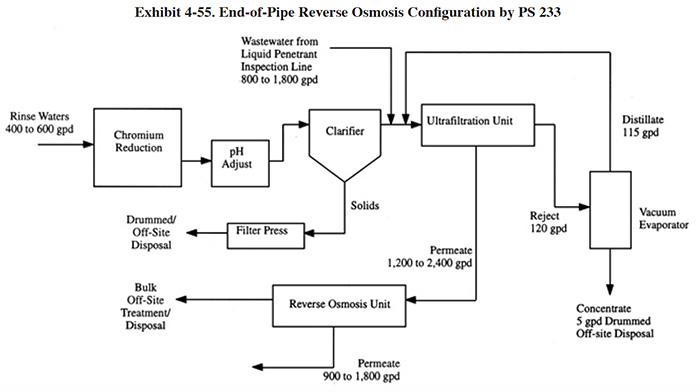
Reverse osmosis is applicable to the recycle of effluent from an end-of-pipe treatment system. End-of-pipe systems that employ hydroxide precipitation generate an effluent that is relatively free of toxic metals; however, it contains a high concentration of total dissolved solids (TDS). A typical effluent contains between 500 to 4,000 mg/l of TDS (ref. Memtek file). Although approximately 1.2% of the shops responding to the Users Survey indicated that they directly reuse this effluent (see Section 3.6), most sources indicate that it is of insufficient quality for rinsing, especially in critical rinse situations. Typically, rinse quality criteria for functional and bright plating is in the range of 100 to 700 mg/l and 5 to 40 mg/l TDS, respectively (Exhibit 3-16). Most end-of-pipe RO wastewater recycle applications consists of: preconditioning to prevent the precipitation of salts in the membrane; prefiltration; RO filtration and storage. One survey respondent used RO and other recycling technologies in place of an end-of-pipe treatment system (PS 233). Their system is described in Exhibit 4-55, where RO is incorporated into a complex, zero discharge configuration. In this application, RO is employed to upgrade the quality of the ultrafiltration permeate so that it can be reused as rinse water. Because this plant operates at zero discharge, the concentrated stream from the RO unit is hauled off-site for treatment/disposal; ordinarily, it would be treated on-site.
 |
RO is generally not considered applicable to highly concentrated, oxidative solutions, like chromic acid, nitric acid and peroxy-sulfuric etchant. Process chemicals in these solutions can be recovered using RO; however, membrane life-span is a concern (ref. 157). The membrane life-span for these applications was demonstrated on a bench scale to be only 15 to 35% of that for nickel plating applications (ref. 157). However, one supplier advertises use of their equipment for chromate conversion coating (ref. KRC file). That company agrees that membrane life is shortened by this application, but indicated that RO is still cost effective. For this application, the primary competing technology is vacuum evaporation.
The unsuccessful chemical recovery applications from the Users Survey included: Watts nickel (PS 172), zinc cyanide (PS 008), acid zinc (PS 010), and copper cyanide (PS 089). The reasons for failure of these systems relate mostly to fouling, and are discussed in subSection 4.7.7.
4.7.4 Technology/Equipment Description
This subsection contains names and/or descriptions of commercially available reverse osmosis equipment that is manufactured and/or sold by vendor survey respondents or discussed in the literature. This is intended to provide the reader with information and data on a cross section of available equipment. Mention of trade names or commercial products is not intended to constitute endorsement for use.
 |
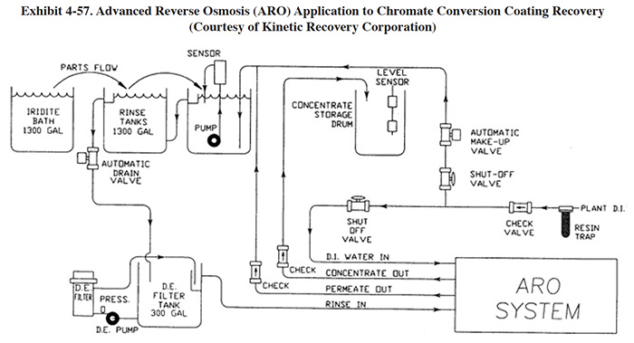 |
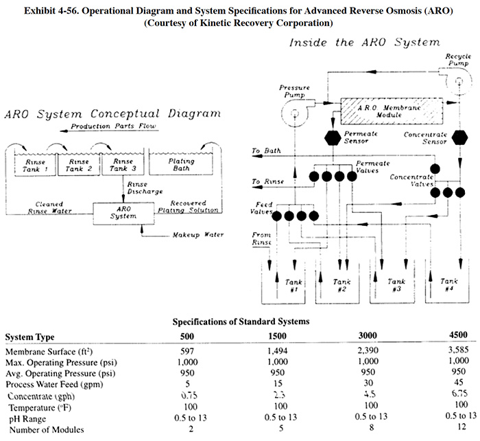
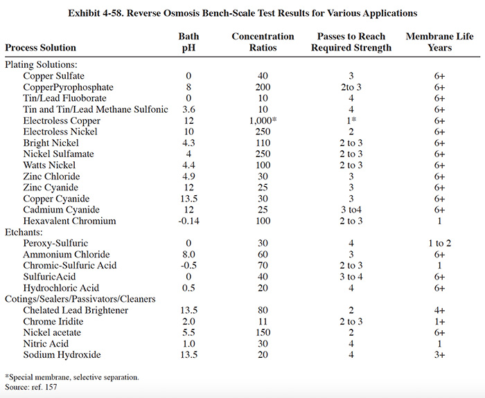
Kinetic Recovery Corporation supplies an advanced reverse osmosis ("ARO") packaged system for chemical recovery from rinse waters. The system consists of: membrane modules (usually two, maximum of three); prefiltration (5 to 10 micron); conductivity controls for rinse water and concentrate quality test; miscellaneous controls (flow, pressure, level) for system automation; recycle and boost pumps for liquid transfer; pressure pumps for liquid/solids separation; internal tanks for concentrate storage; and an electrical control system, including PLC and operator's interface unit. A diagram and system specifications for the ARO system is shown in Exhibit 4-56. A diagram showing a typical layout for chromate conversion coating recovery is shown in Exhibit 4-57. The ARO typically has two membrane modules. The first membrane module is dedicated to the initial feed stream (rinse water) and the second is dedicated to increasing the concentration of the concentrate stream through successive passes. From the first module, the permeate is returned to plating rinses while the concentrate is held in the first internal storage tank. The concentrate is then passed through the second module for further concentrating. The permeate from the second module, depending on its conductivity, is returned to the rinse tank or directed to one of the internal storage tanks. The concentrate moves sequentially through the series of tanks to tank 3, where it is most concentrated, and then is pumped to the bath. The ARO's internal microprocessor changes operating parameters for each pass of concentrate through the second membrane. Pressures and process times are controlled in order to achieve higher concentrated solutions and improve membrane life (ref. 157, Kinetic Recovery Corporation file). The ARO operates in a pressure range of 900 to 1,000 psig, whereas most RO chemical recovery systems operate below 700 psig. According to the manufacturer, an ARO system can concentrate dilute solutions to at or near bath strength without any evaporation or additional concentration technology (however, for most applications a concentration of 40% to 70% of bath strength is targeted) (ref. 157). Results of bench scale tests on various plating and finishing solutions are shown in Exhibit 4-58.
 |
The ARO is the only unit that was advertised for recovery of chromate conversion coating (it is also sold for traditional applications such as nickel plating). These conversion coating baths, which contain chromic acid, are usually operated at low temperatures and therefore, there is little surface evaporation to provide head room for recovered solution. According to the vendor, the multi-pass design and higher operating pressure of the ARO permit this application. Because the first membrane module of the ARO unit contains more dilute rinse waters and the second membrane module contains more concentrated solution, the life-spans of the two module sets are very different. The first module has a life-span of 1 to 2 years and the second module, 4 to 6 months.
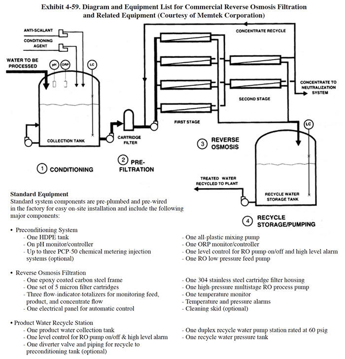 |
Memtek Corporation manufactures an RO wastewater recycle system (Exhibit 4-59). This system is used to upgrade wastewaters from hydroxide precipitation systems for use as rinse water. There are four stages in the system. The first stage is a pre-RO conditioning step where, as necessary, pH adjustment is performed, an anti-scalant chemical is added to prevent precipitation of salts in the membrane elements, reducing agents are added to destroy residual oxidizers, and carbon filtration (optional) removes oxidizers and organics. The second stage is prefiltration, which is achieved by a cartridge filter unit (5 micron). Optional multimedia filtration can be purchased for wastewaters with high suspended solids loadings, where cartridge filters would require frequent replacement. The third step is reverse osmosis filtration. The wastewater is pumped through the unit at 200 to 600 psig, depending on the selection of RO elements. Cellulose acetate or thin film composite elements are used for rejection of dissolved salts. The choice of a membrane element is determined by the chemical characteristics of the wastestream and by the percent recycle desired. The permeate from the RO unit is collected in a storage tank equipped with water recycle pumping equipment. The RO unit is equipped with conductivity monitors to monitor product quality. Optional membrane cleaning systems are available.
4.7. 5 Costs
4.7.5.1 Capital Costs
The capital costs of reverse osmosis units are best expressed in terms of membrane surface area, where the required area for a given chemical recovery application will depend on the flux rate and the percent rejection. Flux is the volume flow of permeate per unit of membrane area, usually expressed as gal/ft2/day or gfd. The percent rejection is defined as follows (ref. 348):
% Rejection = [(feed concentration - permeate concentration)/(feed concentration)] x 100%
Higher percent rejections will result in better quality (i.e., higher purity) permeate and a higher concentration of the plating chemicals. The permeate is typically reused for rinsing and the concentrated chemicals are typically returned to the bath.
In turn, these two factors are affected by the design of the RO equipment and the operating conditions of the system. More specifically, this includes: the type of membrane used, the applied pressure of the RO unit, the number of RO stages, the flow rate of the feed stream, the chemical concentration of the feed stream, and the required concentration of the product returned to the bath.
The feed stream flow to the RO unit is the rinse water, as shown in Exhibit 4-54. The flow rate of this stream and its chemical concentration will depend on the bath concentration, the dragout rate, the required quality of rinse water in the final rinse and the rinsing configuration employed. For example, if dragout recovery rinsing is practiced, the RO membrane surface area will be proportionally reduced by the percentage of dragout returned to the bath by the recovery rinse.
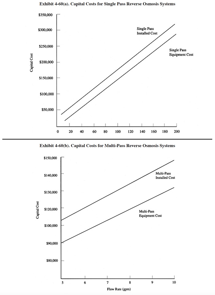 |
Unfortunately, there are insufficient data available to account for the various parameters that impact RO system sizing and cost. Articles and conference papers that describe this technology fail to provide all of the needed data on system components such as membrane area, flux rates, dragout rates, etc. Therefore, at this time, capital costs are simply presented in terms of the feed stream rate (Exhibit 4-60). The multi-pass data include systems with feed stream rates of 5 and 10 gpm and corresponding membrane surface areas of 597 ft2 and 1,194 ft2. The single pass data include systems with feed stream flows of 5 and 200 gpm. These units are applicable to end-of-pipe polishing. No corresponding membrane surface area data were provided for the single pass units.
Most RO units are sold as packaged systems that include a set of membrane modules, feed and recirculation pumps, prefilters, controls, and internal tanks.
 |
4.7.5.2 Operating Costs
The most significant operating costs include O&M labor, energy, chemicals (cleaning) and membrane replacement. Estimates of RO operating costs for single and multi-pass systems are shown in Exhibit 4-61.
4.7.6 Performance Experience
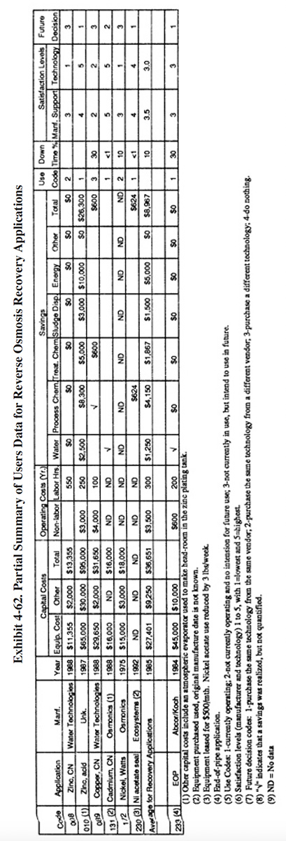
A partial summary of the user data relative to reverse osmosis is presented in Exhibit 4-62. There are a number of observations that can be made from these data and other data contained in the database and literature:
- The average satisfaction level for chemical recovery applications is 3.2 (on a scale of 1 to 5, with 5 being most satisfactory), which is slightly less than the average rating for all recovery technologies (3.4). Only 33% of the shops using RO for chemical recovery indicated that this technology satisfied the need for which it was purchased. The following is a breakdown of the reasons why shops purchased this technology:
To meet of help meet effluent regulations: 4 To reduce plating chemical purchases: 4 To reduce water usage: 2 To reduce the quantity of waste shipped off-site: 2 To reduce wastewater treatment costs: 3 To improve product quantity: 0
- The only recovery applications that were fully successful for survey respondents were: nickel acetate and zinc, acid.
- The use of reverse osmosis as a recovery technology did not impact production quality or the rate of production for the survey respondents. The following responses were provided:
Product Quality Production Rate Improved 0 0 No Change 5 5 Decreased 0 0
- The respondents indicated that, based on their experience with this technology and, if given the opportunity, they would:
Purchase the same technology from the same vendor: 2 Purchase the same technology from a different vendor: 1 Purchase a different technology: 3 Do nothing: 0
- None of the respondents indicated that their reverse osmosis system was the cause of an effluent compliance excursion.
- Although RO application to Watts nickel is a well established application, one of the survey respondents found it to be unsuccessful (PS 172). The supplier stated capacity of their unit was 120 gph and the actual capacity was 50 to 80 gph. PS 172 indicated that their unit did not concentrate the product sufficiently for return to the plating bath.
4.7.7 Operational and Maintenance Experience
The message from the Users Survey respondents with respect to operational and maintenance problems is very clear: RO membranes are highly susceptible to fouling and have relatively short life-spans. As stated by one respondent: "Membrane problems, not enough filtration with (original) unit. Had to add much, much extra filtration ahead of (the RO) unit" (PS 008). The shop using RO as an end-of pipe technology also had membrane fouling problems and frequent membrane replacement (every 3 mth.) (PS 233). They also indicated that their efforts to clean the membrane have been unsuccessful. Short membrane life was identified as a problem by another respondent (PS 172). Membrane fouling by algae was identified as a problem by one respondent (PS 172). Another identified high caustic and carbonate levels as the cause of fouling (PS 089). This shop suggested that carbonate levels must be below 45 g/1 or "some kind of caustic membrane washing must be applied."
RO membranes are susceptible to fouling by suspended solids in the feed stream or materials that precipitate during processing. Solids in the feed stream can be controlled by installing prefilters that are properly selected for the solids encountered and sized for the loading. Precipitation is inhibited by changing operational parameters such as pH. Because pH adjustment of plating chemicals is not usually possible, applications where precipitation may occur should be investigated through bench and/or pilot testing before purchasing equipment.
Two respondents reported no operational or maintenance problems and a percentage downtime of less than 1% (PS 131, PS 230).
A respondent that has eliminated use of their RO unit, indicated that the process "increased solution purification requirements with attendant solution losses, yielding questionable benefits from the technology" (PS 172). It should be noted that any recovery technology that returns both bath chemicals and contaminants to the process tank will cause this problem. However, when contaminants can be removed from the process bath (e.g., carbonates), the benefits of recovery will often outweigh any losses.
4.7.8 Residuals Generation
As discussed in Section 4.7.1, RO separates the feed stream into two components: (1) the permeate which passes through the membrane and (2) the concentrate which retains the dissolved and suspended solids. In typical chemical recovery applications the permeate is used as rinse water and the concentrate is used in the bath. In typical wastewater recycle applications, the permeate is used as rinse water and the concentrate is treated on-site by the end-of-pipe treatment system. In such cases, the quantity of residuals from RO is low, and mostly restricted to used cartridge filters and RO membranes.
The experience of the respondents to the Users Survey was generally the same as described ahove. One respondent indicated that quantity of used filters generated was 0.3 drums per year. That same shop sent 60 to 300 gpy of unspecified "overflow" to off-site treatment (PS 089). The wastes from all other respondents were treated on-site, except for the end-of-pipe, zero discharge application (PS 233). That shop indicated that the reject stream from their RO unit (300 to 600 gpd of concentrated waste with 2.5% total dissolved solids) is hauled off-site for treatment/disposal.
4.8 MESHPAD MIST ELIMINATORS
4.8.1 Overview
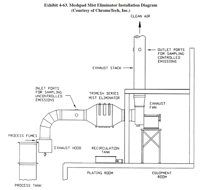
Meshpad mist eliminators are used to recover plating chemicals that become entrained in the airstream that is exhausted from the surface of a plating tank. The primary application of this technology is with chromic acid baths, particularly hard chromium plating and chromic acid anodizing. From the Users Survey, 16 respondents (or 5.0%) indicated that they have employed this technology. Of these responses, there were 16 applications to hard chromium and 2 applications to chromic acid anodizing (two shops used the technology for both applications). The 16 hard chromium applications represent 19.2% of all shops that employ the hard chromium plating process. One manufacturer that responded to the Vendors Survey indicated that they have sold approximately 475 meshpad mist eliminators. Of these units, 63% are installed on hard chromium plating baths, 13% on sulfuric acid baths and the remainder on decorative chromium plating, chromic acid anodizing, caustic, cyanide, hydrochloric acid, and nitric acid baths (ref. Midwest Air Products file).
Meshpad mist eliminators are one of several technologies employed for the removal of plating chemicals from exhausted air. The other two technologies include liquid scrubbers and chevron mist eliminators. Of the three technologies, meshpad mist eliminators are considered to be the most efficient (ref. 213, 404). Other methods of control that may assist in reducing chemical emissions, but are not by themselves adequate control measures, include fume suppressants and polypropylene balls (both are used to cover the surface of the plating tank and reduce mist generation).
The EPA proposed air standards for decorative and hard chromium plating and chromic acid anodizing operations in December, 1993 (ref. 521). The standards are based on the use of scrubbers and meshpad mist eliminators.
 |
 |
Typically, a separate mist eliminator is used for each plating tank, although different configurations are possible. Meshpad mist eliminators are installed within the exhaust system ductwork, as near to the exhaust hood as practical, as shown in Exhibit 4-63. The mist eliminator enlarges the cross-sectional area of the duct which causes a reduced airstream velocity within this section. The reduced velocity permits the entrained droplets of plating solution to impinge on and adhere to the meshpads, thus removing them from the air stream. Having multiple pads in series increases the removal efficiency of the process. The accumulated plating chemicals are periodically washed from the pads (see Exhibit 4-64). This is usually accomplished with an integral water spray system. The liquid from pad washing drains to the bath.
The meshpad mist eliminator technology competes with wet scrubbers and chevron mist eliminators as a control device for chromic acid air emissions. However, with respect to chemical recovery, the meshpad has very little competition from scrubbers. While the recovery of plating chemicals, including chromium, from scrubber systems is possible, scrubber units generally serve multiple types of processes (e.g., cleaning and plating) and the entrapped chemicals are combined, and therefore less amenable to recovery. One recovery strategy that has been employed with scrubbers involves the use of an anion exchange column to collect hexavalent chromium from the scrubber water and to reformulate the resulting sodium chromate regenerant using membrane electrolysis. The resultant products are chromic acid, which is reused as a plating chemical, and sodium hydroxide, which is reused for the anion column regeneration (ref. 402).
4.8.2 Development and Commercialization
Meshpad mist eliminators have been manufactured for more than 30 years (ref. 403) and applied to chromium plating for more than 20 years (e.g., PS 253). However, use of this technology for plating applications only recently became widespread. Until the past few years, most hard chromium shops either had no emission control, used chevron mist eliminators or used wet scrubbers. Most decorative platers relied on fume suppressants and most chromic anodizers either had no controls or used either wet scrubbers or fume suppressants. In 1992, data were presented on the relative uses of these technologies (see Exhibit 4-65) (ref. 213).
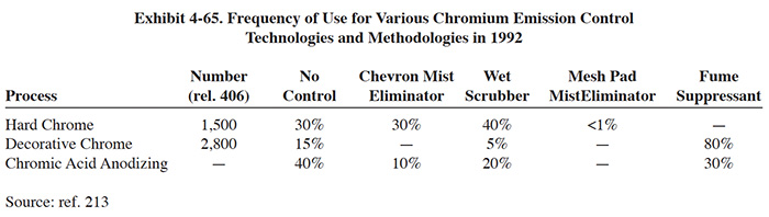 |
The results from the Users Survey show that 86% of the mist eliminator units for which the purchase date was given were installed since 1988 and 71% since 1990. These data and those from the literature indicate that use ot mist eliminators is expanding at a very significant rate. The reason for this change may be due to the recognized advantages of this technology over other competing technologies plus regulatory requirements.
The high efficiency and recovery potential of meshpad mist eliminators was documented by the Navy in the mid-1980's. That work concluded that the meshpad mist eliminator proved to be more effective than a wet scrubber on chromic acid mists and that it produced a concentrated, low volume chromic acid stream with potential for recycle. Further, the Navy concluded that it was a simpler device, compared to the wet scrubber (ref. 404).
The State of California undertook regulatory development efforts in the mid-1980's to control chromium emissions from plating and anodizing (ref. 405). California enacted strict rules on chromic acid emissions in 1988 (ref. 406). The EPA generated and compiled performance data for control measures during the mid-to late 1980's (ref. 46). Included in these efforts were detailed studies of meshpad mist eliminators (ref. 407, 408). These research efforts also showed that high efficiency levels were attained by the meshpad mist eliminator.
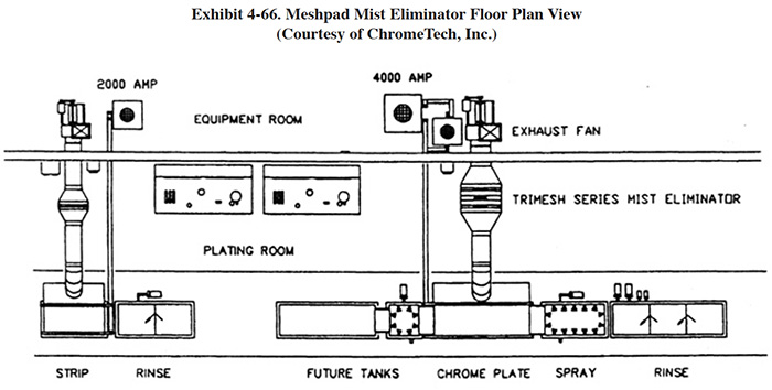 |
4.8.3 Applications and Restrictions
Unlike scrubbers, which are typically installed to serve multiple tanks or processes, meshpad mist eliminators are usually dedicated to individual tanks. Exhibit 4-66 shows a plan view of a hard chrome line where meshpad units are incorporated into the exhaust systems for plating and stripping.
Meshpad mist eliminators can be installed during new plating line installation or as a retrofit to an existing line. With retrofit installations, it is best to include new exhaust fans and ductwork along with the mist eliminators. This ensures proper air pressures and velocities, and allows the ventilation system to be "tuned" for maximum removal efficiency (ref. ChromeTech file).
Some existing shops may have space limitations that preclude the installation of meshpad mist eliminators or cause installation costs to be exorbitant. This is particularly a problem where the existing ductwork is crowded together or obstructed. Also, it is preferable to locate the mist eliminator at an elevation that is higher than the exhaust hood with the air flow in the horizontal direction.
4.8.4 Technology/Equipment Description
This subsection contains a description of commercially available meshpad mist eliminator equipment that is manufactured and/or sold by respondents to the Vendors Survey. This is intended to provide the reader with information and data on a cross section of available equipment. Mention of trade names or commercial products is not intended to constitute endorsement for use.
ChromeTech, Inc. developed and manufactures a Trimesh series mist eliminator (Patent Number 5,200,055) that has been applied to the recovery and control of hard chromium tank emissions. A diagram of the ChromeTech unit was previously shown in Exhibit 4-64.
The first stage is essentially a dry meshpad mist eliminator. Inlet air, heavily laden with chromium, flows through various laminations of woven polypropylene fibers which are contained in the first meshpad cartridge. Most of the chromium (typically 99%) is removed by impingement. As the condensed chrome collects, it is removed from the system through a drain network fitted to the bottom of the unit, and is automatically returned to the plating tank. The small percentage of chrome passing through the first meshpad represents the smallest droplets of the particle-size distribution curve, and is the most difficult to filter with a dry mechanism. Therefore, the second stage of the control device offers a wetted, scrubbing section. Water reservoired in a separate container beneath the device is pumped continuously during plating to the front face of the second meshpad, through atomizing nozzles provided. The pad offers a very large wetted surface area, and chromium mist still entrained in the airstream is dissolved into the recirculating liquid. At regular intervals, typically the end of each plating shift, the chrome that accumulates in this liquid can be returned to the plating tank by using it as the cleaning solvent for the front pad. A considerable amount of evaporation occurs in this stage, typically 2 gph to 5 gph. For this reason, the recirculation tank is fitted with a liquid level control system, and is automatically replenished with deionized water or clean tap water.
The third and final stage is similar to the first - i.e., a single, dry meshpad. The primary purpose of this section is to remove the scrubbing liquor that was administered to the airstream in the previous section. The efficiency of the Trimesh unit was tested by EPA (ref. 407, 408). The results of these two studies showed a consistent removal rate of 98.9 and 99.7%, respectively.
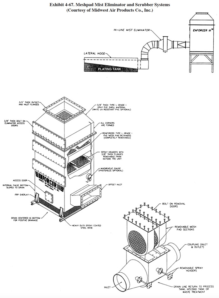 |
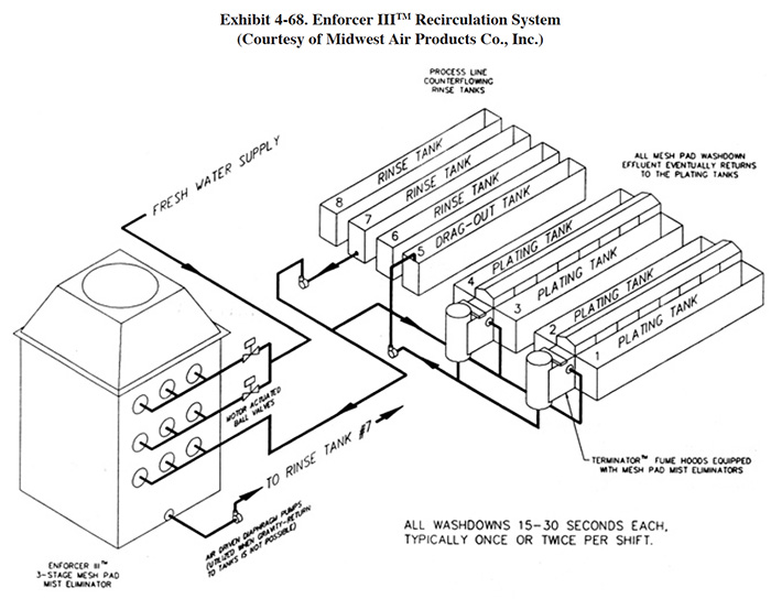 |
Midwest Air Products Co., Inc. manufactures a range of equipment for emission control including fume collection hoods with integral mesh pads (Terminator™), in-line mist eliminators (single and two-stage), mist eliminators utilizing either meshpads or chevron blades, and chromium scrubber units with meshpads (Enforcer III™). They also manufacture mesh pads designed as an integral mist eliminator stage within a packed bed wet scrubber. Two of their products are often combined in series to meet stringent emissions requirements. Diagrams showing their standard chromium scrubber unit (Enforcer III™) with an in-line mist eliminator and details of the mist eliminator and scrubber are presented in Exhibit 4-67. With the meshpad mist eliminator/chromium scrubber configuration, the in-line mist eliminator removes gross quantities of chromic acid and the scrubber unit further cleans the air. The mesh pad mist eliminators can be mounted in either a horizontal or vertical position. Vertical units incorporate a design that prevents washdown from draining down through the duct system. The standard meshpad is manufactured from polypropylene, however, Kynar meshpads are used for most chromic acid applications. As an alternative to the in-line mist eliminator, Midwest Air Products offers a tank exhaust hood that contains a mesh pad (Terminator™) (see Exhibit 4-67). The scrubber unit, which is itself a combined scrubber/mist eliminator, is configured with either three or four mesh pads with each stage designed using specific parameters such as particle size, velocity, removal efficiency requirement and pressure drop. The first pad removes the larger droplets or particles of chemicals and the subsequent stages remove smaller particles. Each mesh pad section is equipped with removable spray headers for periodic washdown. The Enforcer III™ recirculation system is shown in Exhibit 4-68. The first pad is washed with effluent from the scrubber unit or rinse water and subsequent pads are washed with clean water. The effluent is periodically pumped to the plating tank to make up for evaporative losses and to recover the chromic acid.
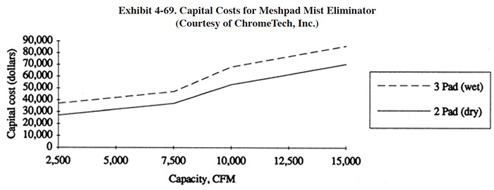 |
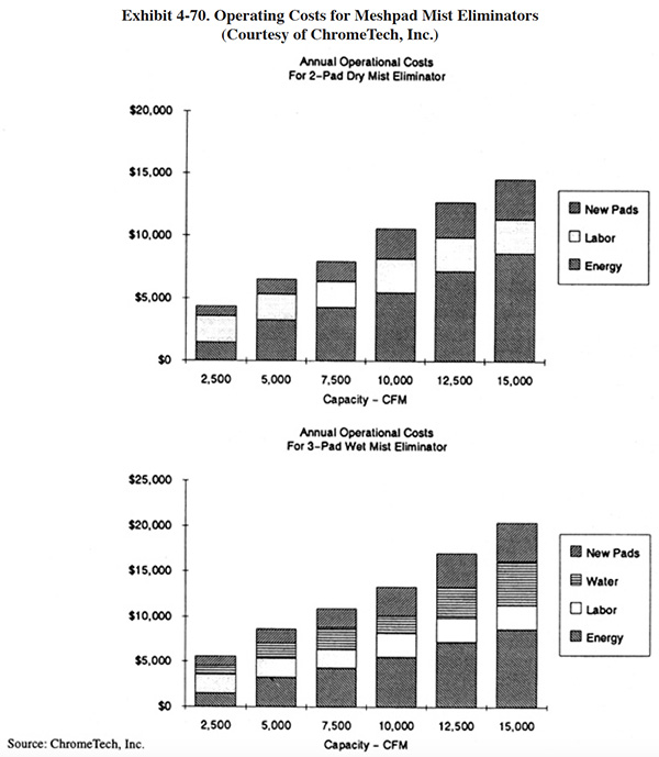 |
4.8.5 Costs
4.8.5.1 Capital Costs
Capital costs for chromium plating tank ventilation systems using meshpad mist eliminators are shown in Exhibit 4-69. The capital costs include the tank hood, ductwork, mist eliminator, water recirculation system and exhaust fan. The cost curves are based on two types of systems: (1) a 3-pad wet system and (2) a 2-pad dry system. Basic equipment and installation equipment costs are shown for both types of systems.
4.8.5.2 Operating Costs
Operating costs for mesh pad mist eliminators are shown in Exhibit 4-70 for 3-pad wet and 2-pad dry systems. The operating costs are based on 4,000 hr/yr of operation. Energy costs are for the exhaust fan and water recirculation pump.
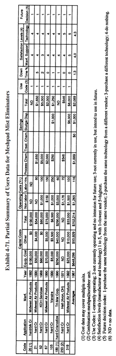 |
4.8.6 Performance Experience
Eight respondents to the Users Survey provided some detailed data covering their experience with the meshpad mist eliminator technology. A summary of their responses are shown in Exhibit 4-71 and discussed in this section.
- Meshpad mist eliminators had the highest average satisfaction level among recovery technologies (4.1 on a scale of 1 to 5, with 5 being most satisfactory). Also, all respondents indicated that this technology satisfied the need for which it was purchased. The following is a breakdown of the reasons why shops purchased this technology (multiple responses given by some shops):
To meet or help meet effluent regulations: 4 To reduce plating chemical purchases: 5 To reduce the quantity of waste shipped off-site: 2 To reduce wastewater treatment costs: 2 To improve product quantity: 1 Reduce emissions or meet air standards: 3
- The use of meshpad mist eliminators for chromium recovery generally did not impact production quality or the rate of production. The following responses were provided:
Product Quality Production Rate Improved 1 1 No Change 5 5 Decreased 0 0
- All plating shops providing responses indicated that, based on their experience with this technology, they would purchase the same type of equipment from the same vendor. The following is a breakdown of their responses:
Purchase the same technology from the same vendor: 7 Purchase the same technology from a different vendor: 0 Purchase a different technology: 0 Do nothing: 0
- None of the shops indicated that a meshpad mist eliminator was the cause of an effluent compliance excursion.
- The major savings from the operation of a meshpad mist eliminator was the result of reductions in bath chemical use. The reported chemical savings ranged from $250 to $5,000 per year. One shop/also reported a $1,000 per year savings due to reduced sludge disposal costs.
4.8.7 Operational and Maintenance Experience
The following summarizes the respondent's O&M experiences and provides operating labor information.
- Seven shops provided operating labor data. For these shops, the average number of annual O&M hours for meshpad mist eliminators were: 116 hrs/yr (for several of the respondents this includes O&M labor for multiple units). The skill requirement most commonly needed for operating this technology is a trained technician. The following is a breakdown of the responses for skill requirements (based on data from seven respondents, some respondents gave multiple responses):
Environmental Engineer: 0 Process/Chemical Engineer: 0 Chemist: 0 Consultant: 1 Plumber/Pipe Fitter: 1 Electrician: 1 Vendor: 0 Senior-Level Plater: 2 Junior-Level Plater: 1 Trained Technician: 5 Wastewater Treatment Plant Operator: 0 Common Labor: 2 Other: 0
- In general, meshpad mist eliminator equipment requires little maintenance and has a relatively long equipment life. Most shops indicated that the downtime for this technology was low or non-existent and none identified any major O&M problems. Long equipment life was evidenced by the fact that no shops responding to the survey indicated that they had previously used this process and subsequently discarded it. All of the identified units were in operation at the time of the survey. The oldest systems identified in the survey were purchased in 1971. All other units were purchased within the past five years.
- The following specific O&M problems were reported. PS 021 indicated that their first stage pad partially failed. PS 067 also reported a meshpad failure ("disintegration"). PS 052 reported occasional leaks in the associated ductwork, whichthey patch themselves. PS 105, which reported the highest O&M labor requirement (250 hrs/yr), indicated that their unit needs daily attention, but that it is minimal.
4.8.8 Residuals Generation
When used as a recovery technology, the meshpad mist eliminator generally does not generate a residual. Chemicals captured by the meshpads are returned to the process tank during pad wash-down. None of the shops responding the survey reported a generation of residuals, other than the recovered wash-down stream.
 |
 |
 |
The information contained in this site is provided for your review and convenience. It is not intended to provide legal advice with respect to any federal, state, or local regulation.
You should consult with legal counsel and appropriate authorities before interpreting any regulations or undertaking any specific course of action.
Please note that many of the regulatory discussions on STERC refer to federal regulations. In many cases, states or local governments have promulgated relevant rules and standards
that are different and/or more stringent than the federal regulations. Therefore, to assure full compliance, you should investigate and comply with all applicable federal, state and local regulations.