 |
Section 7
Wastewater Treatment
7.1 INTRODUCTION
Section 7 covers end-of-pipe (EOP) wastewater treatment. Most of the respondents to the Users Survey employ conventional EOP wastewater treatment and sludge handling processes. These processes, which are so named because of their wide usage throughout the plating industry, are defined and discussed in Section 7.2. Capital and operating costs for conventional treatment are addressed in Section 7.3. End-of-pipe treatment data from the Users Survey are presented in Section 7.4. Some shops employ non-standard methods of end-of-pipe treatment. For metals removal/concentration, the non-standard methods that are used by survey respondents are ion exchange, evaporation and microfiltration. These three technologies are discussed in Section 7.5.
7.2 CONVENTIONAL TREATMENT TECHNOLOGIES
7.2.1 Overview
Conventional treatment is a series of unit processes used extensively by industry that have provided reliable treatment for many electroplating operations. Exhibit 7-1 is a schematic of a conventional treatment system for electroplating wastes containing chromium and cyanides in addition to other heavy metals, acids, and alkalis.
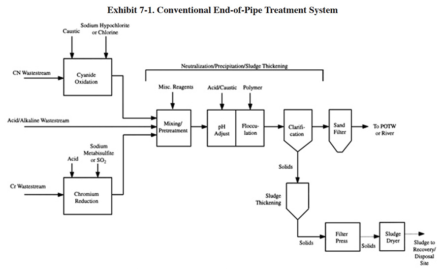 |
The configuration of conventional treatment is relatively standard. It consists generally of the following unit processes:
- Chromium reduction of segregated chromium waste streams to reduce the chromium from its hexavalent form to the trivalent state, which can be subsequently precipitated as chromium hydroxide by additions of alkali.
- Cyanide oxidation of segregated cyanide-bearing waste streams to oxidize the toxic cyanides to harmless carbon and nitrogen compounds.
- Metals removal of the combined metal-bearing wastewaters using hydroxide precipitation techniques.
- Sludge dewatering using gravity thickening followed by a mechanical dewatering device to increase the solids content of the sludge and therefore reduce its volume. Within the past five years, thermal dehydration using sludge dryers has also become a conventional unit operation. This equipment further increases the solids content of the sludge.
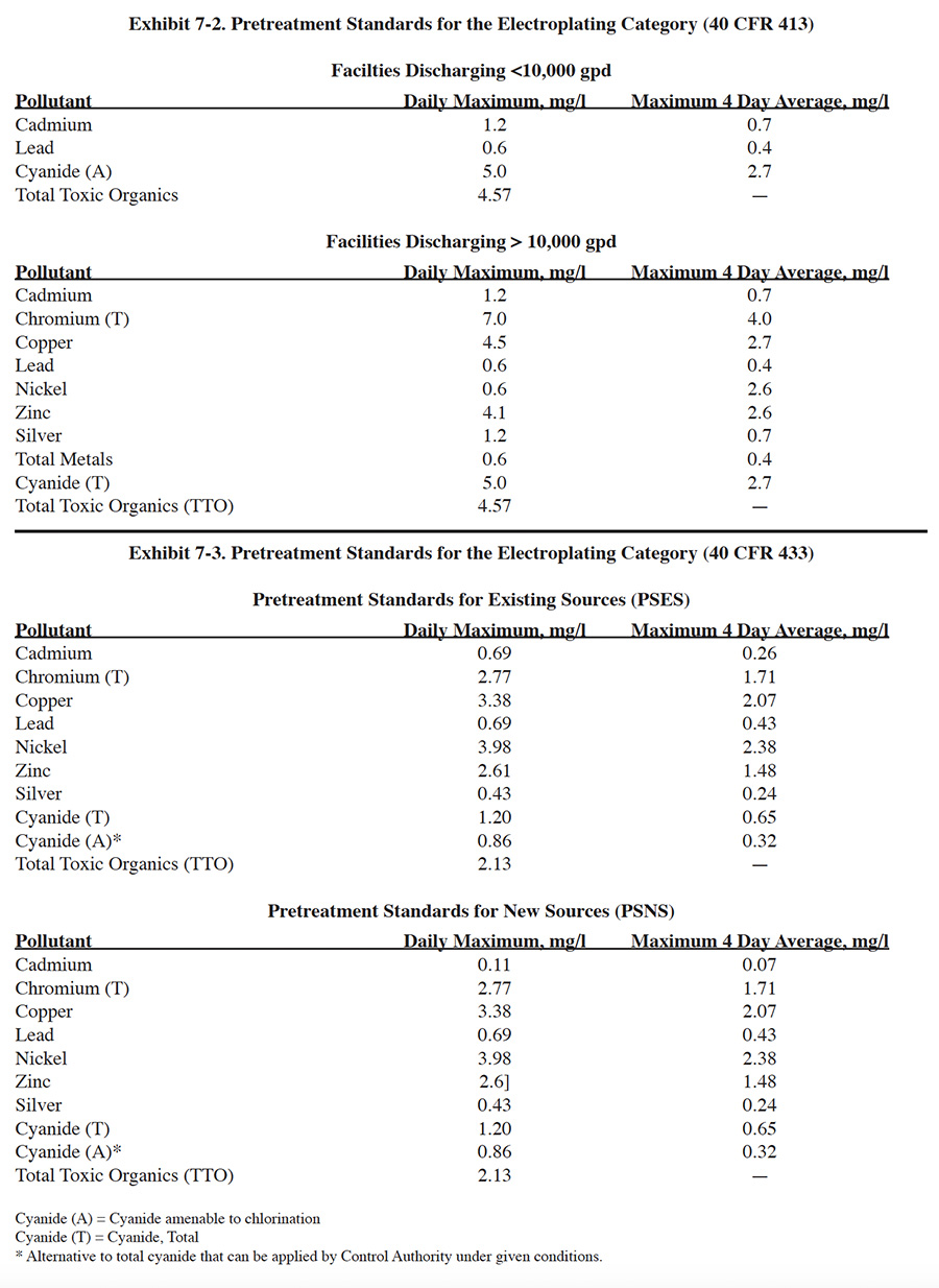
The Federal electroplating and metal finishing pretreatment wastewater standards (Exhibits 7-2 and 7-3) were developed by EPA by identifying commonly used treatment practices and determining their effectiveness by collecting effluent data from well operated systems. Conventional treatment was selected by EPA as the standard system. Therefore, for most plating shops, use of conventional treatment will provide sufficient pollutant removal to meet discharge standards.
 |
There are two major exceptions to this rule. First, many plating shops are regulated by local discharge standards that are more stringent than the Federal standards and conventional treatment may be insufficient to meet these limitations. Second, the treatment systems selected by EPA for establishing the Federal standards were those systems that EPA determined to be "properly operating facilities." For example, EPA omitted facilities that: (1) did not have well operated treatment processes; (2) had complexing agents (e.g., non-segregated wastes from electroless plating); and (3) had dilution from non-plating wastewaters. As a result, some plating facilities may not meet the properly operated facility criteria used by EPA and may have difficulty meeting Federal standards using conventional treatment.
In cases where conventional treatment is insufficient to meet discharge limitations for a given facility, there are three basic choices for attaining compliance: (1) correct or upgrade the existing processes; (2) make internal changes (e.g., improve rinsing, add recovery, segregation of waste streams) to "normalize" the wastewater, (3) use conventional treatment plus additional treatment (i.e., polishing), and (4) use alternative treatment processes. Information on treatment system operation is reviewed in this section and details can be found in the literature (e.g., ref. 38). Methods for internal changes are discussed in Sections 3, 4, 5 and 6. Additional and alternative treatment processes are discussed in this section.
7.2.2 Chromium Reduction
Various metal finishing processes contribute chromium to the wastewater. Among these are chromium plating, chromating, bright dipping, chromic acid anodizing and chromium stripping. Although chromium is present in both the trivalent (Cr+3) and hexavalent (Cr+6) state in process solutions and wastes, the dominant species is Cr+6. Unlike most heavy metals which are precipitated readily as insoluble hydroxides by pH adjustment, Cr+6 must first be reduced to the trivalent state because it forms the chromate complex which behaves as an anion and cannot form an insoluble hydroxide (ref. 38).
Conventional chromium reduction is achieved by reaction of Cr+6 with a reducing agent. The most commonly used reducing agents are sulfur dioxide gas and sodium metabisulfite (dry granular power). Alternative reducing agents include: sodium hydrosulfite, ferrous sulfate and iron or steel scrap (ref. 38). The chemical equations applicable to reduction with sulfur dioxide and sodium metabisulfite (actually sodium bisulfite, which is formed when sodium metabisulfite is added to water) are (ref. 38, 413):
 |
Sulfur Dioxide Gas:
3SO2 + 2H2CrO4- → Cr2(SO4)3 + 2HOHSodium Bisulfite:
3NaHSO3 + 2H2CrO4 + 3H2SO4 →
Cr2(SO4)3 + 5HOH + 3NaHSO4
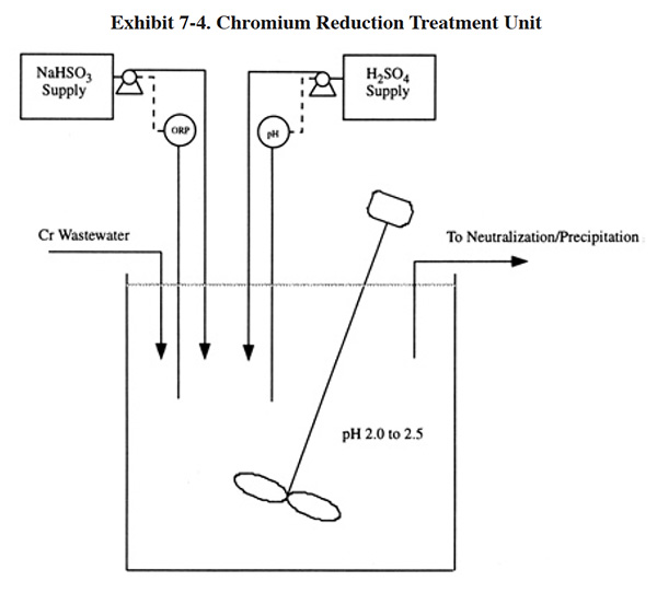
A typical chromium reduction process is shown in Exhibit 7-4. The basic equipment includes a reaction tank, mixer, chemical feed system, pH meter/controller, an oxidation reduction potential (ORP) meter/controller, transfer pumps and level controls.
The type of chemical feed system selected will depend on the reduction reagent selected. Sulfur dioxide gas usage is restricted mostly to large treatment plants and sodium bisulfite is used at most small and medium-sized systems, but it is also used at large systems. Sulfur dioxide gas is the reagent of choice for larger systems due mainly to its lower chemical cost (at high feed rates it is nearly 50% less expensive, see Section 7.3.2). However, its use has drawbacks that cause it to be less desirable for smaller systems; these are: (1) requires a more expensive chemical feed system (sulfonator) and (2) presents a health hazard. The latter of these factors is the result of the toxic nature of sulfur dioxide gas. To overcome the health hazard, many large facilities install a vacuum system to prevent losses of sulfur dioxide to the working area, which further increases the capital cost of using this reagent. The results of the Users Survey indicate that approximately 6% of all respondents use sulfur dioxide and approximately 60% of all respondents use sodium bisulfite (approximately 34% do not have a chromium treatment process or use an alternative chemical). Shops using sulfur dioxide had average and median industrial wastewater flow rates of 153,814 gpd and 55,000 gpd, respectively. For all shops surveyed, the average and median flows were 34,600 gpd and 14,000 gpd.
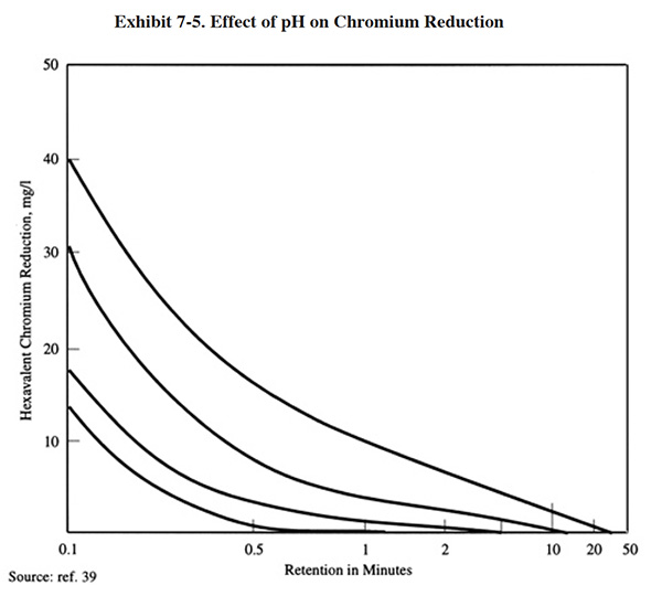 |
The efficiency of the reduction reaction is highly dependent on pH (Exhibit 7-5), and most conventional processes are operated between pH 2.0 and 3.0. Since the incoming wastewater is usually above this desired range, sulfuric acid is added to reduce the pH. This is a drawback of the conventional process since the subsequent metal removal step is performed at an elevated pH (typically 7.0 to 9.5), and therefore the introduction of acid increases the subsequent need for alkali reagent.
The conventional chromium reduction processes are capable of producing an effluent with less than 0.1 mg/l Cr+6 (ref. 39).
The theoretical quantity of sodium bisulfite or sulfur dioxide required to reduce one pound of hexavalent chromium is approximately 3 lbs and 2 lbs, respectively. One source estimates that 0.2 lbs of sulfuric acid are required to lower the pH to the required range of 2.0 to 3.0 (ref. 392). The results of the Users Survey indicate that actual chemical requirements for chromium reduction and pH adjustment are much greater than the theoretical or estimated quantities presented by most references. In fact actual dosages are often five to ten times or more than theoretical dosages. Treatment chemical usage data from survey respondents is presented and discussed in Section 7.3.2.
The following is a discussion of two alternative methods to the conventional sulfur compound chromium reduction process that are in use by the metal finishing industry: the sacrificial iron anode and sulfate reduction methods.
The sacrificial iron anode technology makes use of an electrochemical reaction in which an electrical current is applied to consumable iron electrodes. The electrochemical cell consists of a number of 1/8 in. cold rolled carbon steel plates separated by 1/8 in. gaps. A DC power supply is connected across the two end plates. Wastewater flows through the gaps in contact with the electrodes allowing the current to flow from electrode to electrode. The current flow causes the anode to dissolve slowly, thereby generating ferrous ions into the wastewater stream. The ferrous iron chemically reacts with the hexavalent chromium and reduces it to the trivalent state. During this reduction process, the iron is converted to trivalent iron hydroxide which results in a co-precipitation effect, where the iron hydroxide adsorbs heavy metal cations onto its surface (ref. 412). The process has the advantage of being able to reduce chromium at neutral pH. A drawback is that the process produces ferric hydroxides, which increases the quantity of sludge (ref. 39). Five respondents to the Users Survey (1.6%) use this technology (PS 083, PS 181, PS 240, PS 244 and PS 300). These systems, which were purchased between 1983 and 1991, were given satisfaction ratings of 3 and 4 (on a scale of 1 to 5, with 5 being the highest level of satisfaction) (three respondents did not provide a satisfaction rating). One of the technology users indicated that they purchase approximately $2,000 of replacement electrodes per year for their sacrificial iron anode unit (PS 083). This shop has a chromium bearing wastewater flow of 8,000 to 10,000 gpd. Another shop purchases approximately 2,900 lbs/yr of iron ($1.35/lb). This shop has a total plating flow of 25,810 gpd.
Ferrous sulfate reduction has been used to reduce chromate in an acid environment for a number of years. The primary advantage for many facilities was an inexpensive, abundant supply of ferrous sulfate, which is a waste product from steel pickling. The disadvantage of the process is the considerable increase in sludge generation owing to the precipitation of ferric hydroxide in the neutralization phase of the treatment. Pilot evaluations during the early 1980's of alkaline ferrous sulfate reduction of chromate were relatively successful. The process was proven capable of rapid reduction at pH levels between 8 to 10. The advantage of the alkaline process is the savings in sulfuric acid and caustic that are used with the conventional reduction process to lower and subsequently raise the pH. Also, the reduction process can be accomplished in the same reaction vessel as neutralization, which reduces equipment requirements (ref. 39). However, the process still has unfavorable sludge generation characteristics and a lack of control in chemical metering (ref. 348). The use of ferrous sulfate as a hexavalent chromium reducing compound was reported by only two respondents to the Users Survey (PS 020 and PS 135). At least one of those shops performs reduction in an alkaline environment (PS 135). Also, ferrous sulfate is used by approximately 3.1% of all respondents for co-precipitation. Sodium hydrosulfite is also used by one respondent as a chromium reducing agent in an alkaline environment (PS 173 and PS 253). PS 253 treats a 28,300 gpd chromium wastestream containing an average of 68.3 mg/l Cr. This shop uses 12,400 lbs/yr of sodium hydrosulfite in their chromium reduction process.
7.2.3 Cyanide Oxidation
Nearly all electroplating shops that generate dilute cyanide bearing wastewaters employ alkaline chlorination treatment. This process, which has been in commercial use for over 35 years, is suitable for destroying free dissolved hydrogen cyanide and for oxidizing all simple and some complex inorganic cyanides in aqueous media (ref. 348). If properly designed, maintained and operated (good pH and oxidation reduction potential control), the process will oxidize cyanides which are amenable to chlorination (i.e., the cyanide that can be oxidized by the alkaline chlorination process), to less than 1.0 mg/l cyanide (ref. 39). Extensive sampling by EPA showed that the average effluent concentration from a well operated cyanide destruction system contains 0.18 mg/l of total CN and 0.06 mg/l of amenable CN.
The cyanide in very stable complexes, such as ferrocyanides or ferricyanides, is basically unaffected by chlorination (ref. 243). Cyanide that is complexed with copper, nickel and precious metals is amenable to chlorination, but reacts more slowly than free cyanide and therefore requires excess chlorine for efficient cyanide destruction. Concentrated cyanide wastes, such as spent plating or stripping solutions, should not be reacted with hypochlorite because the reaction can be violent, with the emission of chlorine gas. These wastes can be batch treated by electrolytic oxidation and thermal destruction (ref. 242).
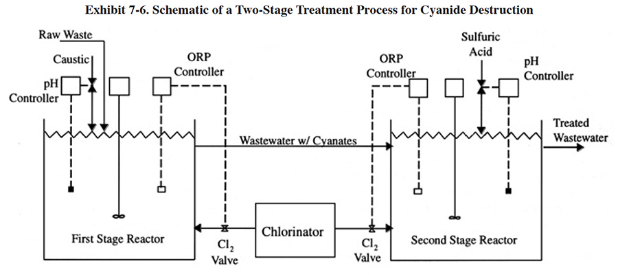 |
A schematic of an alkaline chlorination process is shown in Exhibit 7-6. Most often the process is operated in two stages, with separate tanks for each stage. A common exception is batch treatment systems, where one tank is typically employed (ref. 38). Destruction of dilute solutions of cyanide by chlorination can be accomplished by direct addition of sodium hypochlorite (NaOCl), or by addition of chlorine gas plus sodium hydroxide (NaOH) to the wastewater. With direct chlorine gas addition, sodium hydroxide reacts with the chlorine to form sodium hypochlorite. Selection between the two methods is based primarily on economics and safety. The chemical costs for chlorine gas treatment are less than half those of direct hypochlorite addition (see Section 7.3.2), but handling is perceived to be more dangerous and equipment costs are higher (ref. 39). Relative to the safety issue, one expert source argues that modern gas handling equipment is highly reliable and designed to be relatively fail safe (ref. 38). The results of the Users Survey indicate that 95% of the respondents with alkaline chlorination processes use sodium hypochlorite and 5% use chlorine gas plus sodium hydroxide. The shops that use chlorine gas tend to be the same shops that select sulfur dioxide for chromium reduction (e.g., PS 025 and PS 093). Generally, these shops have substantial cyanide wastestream flow rates.
In the first stage of treatment, hypochlorite oxidizes cyanide to cyanate. This reaction is accomplished most completely and rapidly under alkaline conditions at pH 10 or higher (preferred range is 11.0 to 11.5) (ref. 38). An oxidation period of 10 to 15 minutes is usually adequate (ref. 38); however retention times up to 60 minutes are routinely used (ref. 39, 348). An ORP set-point of approximately +325 millivolts is adequate for most operations. A higher set-point may be needed, depending on the composition of the wastewater. A set-point of +400 millivolts is considered a maximum point (ref. 38). Potassium iodide-starch test paper, which indicates residual chlorine, is sometimes used to determine if the reaction is complete (ref. 243). To avoid producing solid cyanide precipitates, which may resist chlorination, the wastewater should be continuously and vigorously mixed during treatment (ref. 38, 39). The resulting cyanate is further oxidized to carbon dioxide and nitrogen in the second stage. In this stage, the pH is lowered to approximately 8.5 and additional hypochlorite is added. An ORP reading of +600 to +800 generally signals a complete reaction. The retention time of the second stage is typically 30 to 60 minutes; however, times of 120 minutes are sometimes specified (ref. Delta Pollution Control File).
Although a two-tank system is preferred, complete cyanide oxidation to carbon dioxide and nitrogen can be accomplished in a single-stage unit, provided close pH control is maintained (ref. 39).
When sodium hypochlorite is used, the reaction in the first stage is:
NaCN + NaOCl --> NaCNO + NaCl
and in the second stage,
2NaCNO + 3NaOCl + H2O --> 3NaCl + N2 + 2NaHCO3
Sodium hypochlorite consumption is usually estimated to be 25 to 100 percent greater than the stoichiometric requirement (approximately 7 lbs of Cl2 or 7.5 lbs of NaOCl per lb of CN); where the excess is consumed by oxidation of organics and raising the valences of metals in the wastewater (ref. 39). The results of the Users Survey indicate that most shops are using substantially higher dosages (up to five hundred percent or more). Higher dosages by respondents may be the result of the formation of metal complexes (e.g., due to inadvertently combining cyanide and nickel or iron bearing wastewaters, use of unlined steel tanks, use of steel anode baskets and not retrieving fallen parts from tank bottoms) and/or poor pH control during treatment. The latter reason is especially apparent for several shops that operate single stage cyanide destruction processes and do not add acid to lower the pH. As a result, the second part of the oxidation reaction is slow and operators probably add higher dosages of NaOCl to compensate for the speed of the reaction. Shops operating under these conditions include: PS 058, PS 135, PS 204 and PS 210. It should be noted that acid additions must be made under the correct conditions or a severe safety problem could arise. Dilute acid is sometimes used in place of concentrated acid to reduce the danger of operating this process (ref. 243). Also, some equipment vendors provide a caustic feed capability that is controlled by an independent set-point, usually at a pH of 7.5 (ref. 38). The use of acid in the alkaline chlorination process is discussed by Roy (ref. 38).
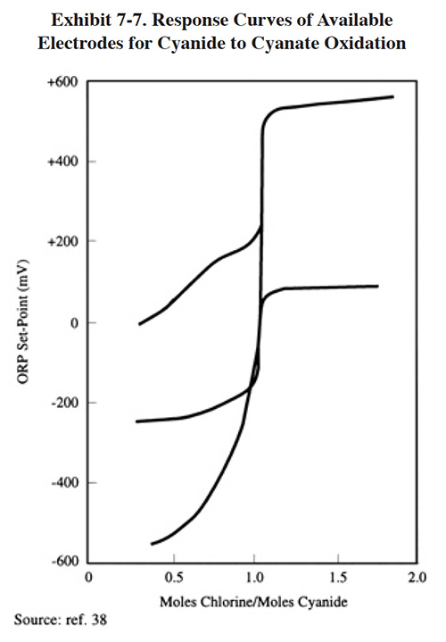 |
Alkaline chlorination systems have generally proven reliable if well maintained. Use of a well-designed ORP control system is highly recommended. Most problems with the system focus on failures of this element. Exhibit 7-7 shows the response of various electrodes to the cyanide-to-cyanate reaction end point. The graph shows that the gold-plated electrode, although more expensive, gives much better reagent addition control (ref. 39).
There are several alternatives to the alkaline chlorination process. These are discussed in the following paragraphs.
Ozone oxidation of cyanide has been practiced as a substitute technology for alkaline chlorination. It is effective in destroying cyanide to the levels required by EPA. The advantage of using ozone lies in reduced operating costs. Ozone is generated on-site (typically by the silent electrical discharge method) and is less expensive than chlorine or sodium hypochlorite. The equipment cost is significantly higher, however, owing to the expense of an ozone generator. Another disadvantage of the process is that it does not oxidize cyanide past the cyanate stage, unless excess ozone is used. Ozone oxidation requires 1.8 to 2.0 lbs of ozone per pound of CN to reach the cyanate stage and 4.6 to 5.0 lbs to reach complete oxidation. An advantage of ozone oxidation is the absence of chlorine that can combine with organics present in the wastewater to produce toxic compounds (ref. 39). Another advantage is the ability of ozone to destroy zinc, copper and nickel cyanide complexes (ref. 243). The ozonation process has also been combined with UV radiation for the treatment of halogenated organics (ref. 348, 386). None of the respondents to the Users Survey employ ozone oxidation of cyanides.
Other alternatives to alkaline chlorination include: alternative chemistries; electrochemical oxidation; thermal oxidation; and precipitation.
Alternative chemistries include hydrogen peroxide (PS 020 and PS 273) (ref. 386) and calcium hypochlorite (PS 174).
Electrochemical oxidation is sometimes used to destroy concentrated cyanide wastes (e.g., >50,000 mg/l CN). A description of the required equipment, including a small commercial unit, is presented in AESF literature (PS 243).
Thermal treatment of cyanide wastes is performed by two of the respondents to the Users Survey (PS 142 and PS 245). Their equipment is provided on a rental basis by Cyanide Destruct Systems (Canada). The equipment can be purchased for $40,000 or rented for $600 per week. PS 142 also indicated that they required a facility modification/ancillary equipment purchase costing of $700. The equipment is intended for concentrated cyanide wastes (at both shops dilute CN wastes are treated by alkaline chlorination). The rental unit is essentially a heated pressure chamber (35 gal, 450 to 470°F, 600 psi) with an agitator. PS 142 used the unit to treat cyanide wastes containing 100,000 mg/l CN to approximately 25 mg/l. Disposal costs for these wastes were previously $800 to $1,000 per 55-gal drum. In operation, CN wastes are transferred into the vessel and treated on a batch basis for 10 hours and then discharged to conventional treatment. Ammonia gas generated by the unit is vented to the atmosphere. PS 142 reported operating costs, excluding labor, of $4,000 per year and a labor requirement of 750 man-hours. They also indicated that they experienced temperature and pressure control problems due to a seal leak (N2 and oil seal) at the point of agitator entry into the vessel. PS 142 indicated that the unit had a downtime of 50% and that they have discontinued its use.
Chemical precipitation of cyanide can be achieved using ferrous sulfate. This process precipitates the cyanide as a ferrocyanide, which can be removed in a subsequent sedimentation process (ref. 386). Results of EPA sampling of such a process showed that an average influent concentration of 2.7 mg/l CN was treated to 0.023 mg/l CN.
7.2.4 Metals Removal
Hydroxide precipitation is the standard method of removing heavy metals from wastewater. This is achieved by adjusting the pH of the wastewater with an alkaline reagent to reduce the solubility of the dissolved metals and settling and removing the resultant metal hydroxide precipitates. Seventy-five percent of the respondents to the Users Survey employ this process. The metals removal process is often divided into four steps: (1) pretreatment; (2) precipitation; (3) flocculation; and (4) settling. Each of these steps will be discussed in this subsection, with reference to the methods and chemicals employed by survey respondents.
7.2.4.1 Pretreatment
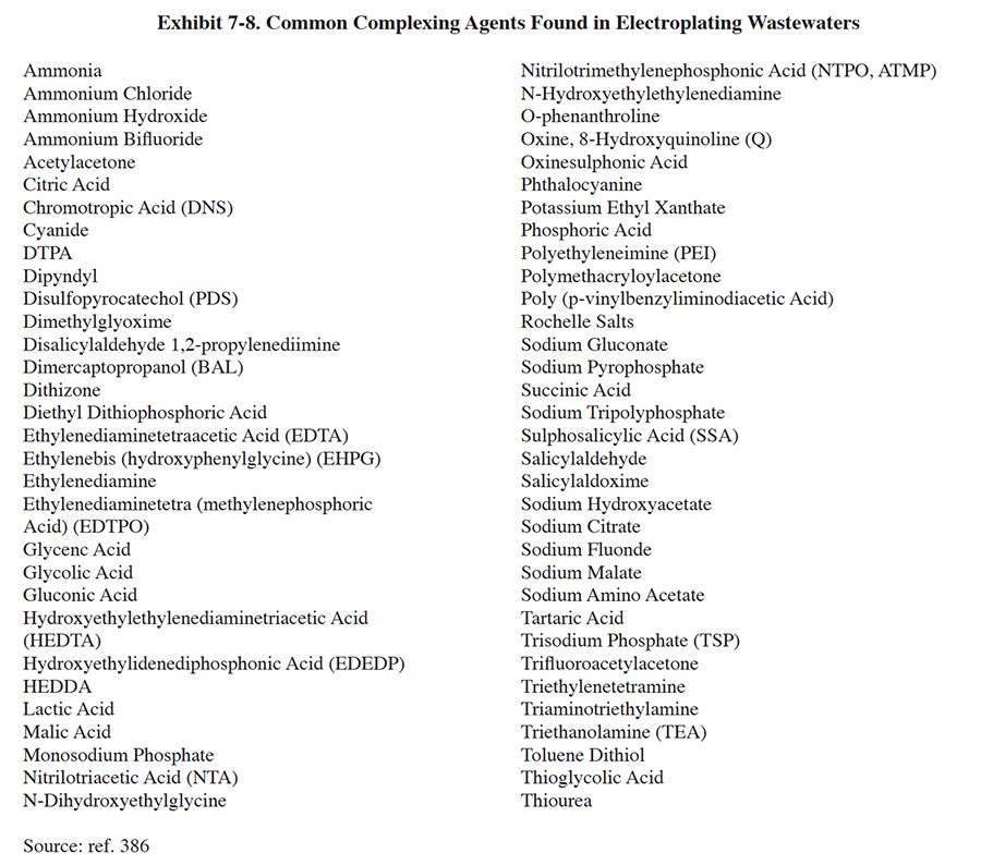
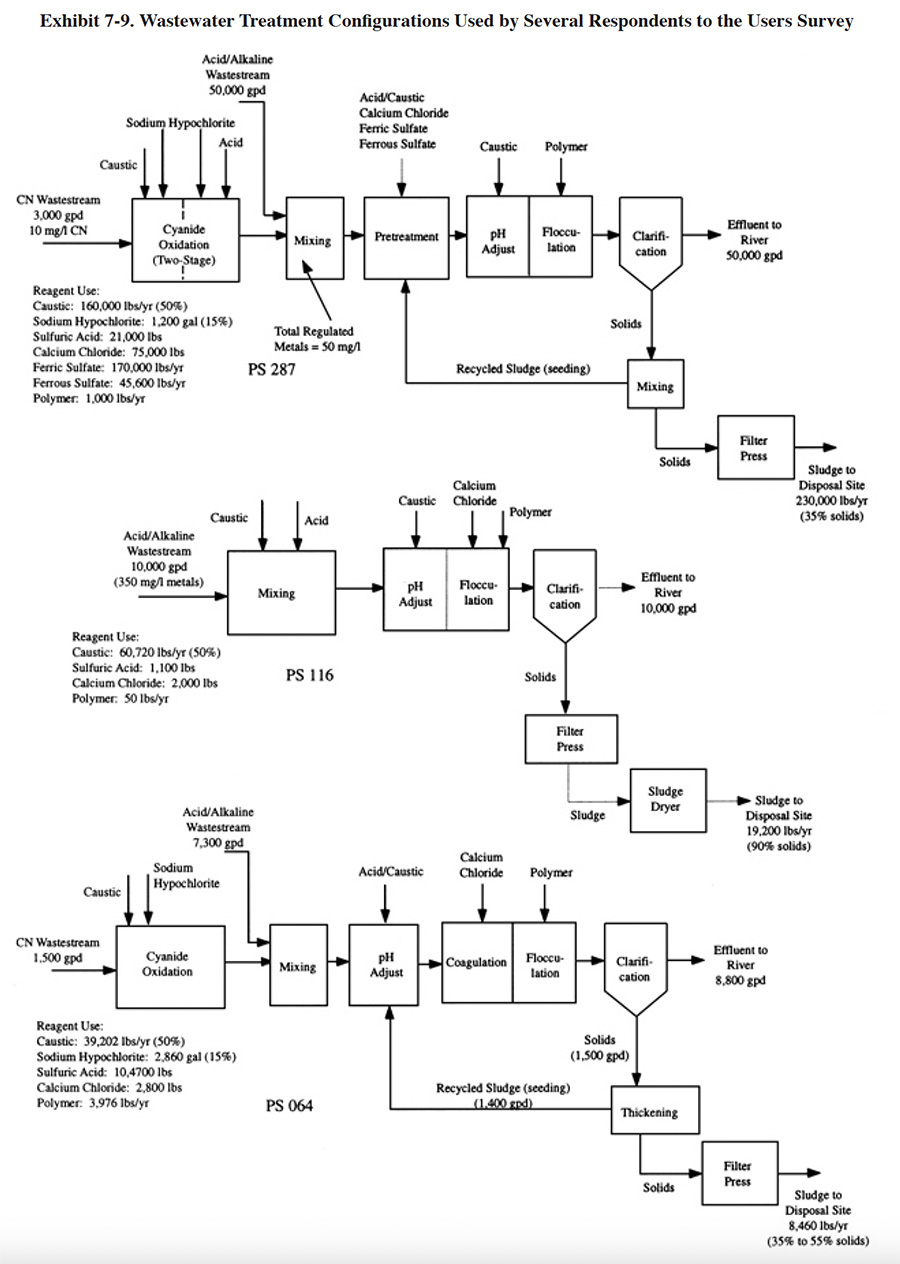
Prior to metals precipitation, many shops use "pretreatment" processes to affect substances that require special treatment or interfere with subsequent treatments. Common metal complexing compounds which will cause interference are listed in Exhibit 7-8. Some shops combine this step with the precipitation and/or flocculation steps. Exhibit 7-9 (PS 064, PS 116, PS 287) shows several configurations for pretreatment or co-treatment using various chemicals. Approximately 45% of the survey respondents use some form of precipitation aid (not including polymer, which is employed by nearly every shop to aid in flocculation). Chemicals used by survey respondents prior to or during metals precipitation include ferrous sulfate, sodium hydrosulfite, aluminum sulfate, soda ash and sodium dithiocarbamate (DTC). Ferrous sulfate is sometimes added to function as a reducing agent, but more often to provide co-precipitation for the removal of metals from chelated wastewaters. With the latter application, complexed metals are co-precipitated with ferric hydroxides. While being an effective metals removal method, this process generates approximately four times as much sludge as sodium hydroxide alone (ref. 144). Calcium chloride and aluminum sulfate are typically used during a pretreatment step (they are often used together1 because the combined results are better than for either one used alone) for the removal of fluoride, phosphate, silicates and/or emulsified oil (ref. 38).
 |
 |
7.2.4.2 Precipitation
Precipitation is the process by which dissolved metals are made insoluble, usually as metal hydroxides. With metal finishing wastewaters this is brought about by the addition of alkali treatment reagents. Two alkalis are most commonly used for hydroxide precipitation: sodium hydroxide (i.e., NaOH, or, as it is commonly referred to, caustic soda or simply caustic) and lime (i.e., calcium hydroxide or hydrated lime, Ca(OH)2). Of the survey respondents that have metals precipitation processes, 84% use caustic only, 5% use lime only and 9% use a combination of caustic and lime. Several other treatment reagents are used as either the sole alkali ingredient or as an adjunct to caustic or lime. The other primary alkalis are magnesium hydroxide (used by 4.3% of all respondents that perform metals precipitation, but not as the sole source of alkali) and calcium chloride (used by 11.9% of respondents that perform metals precipitation, but only 2% use it as their sole source of alkali). Other alkalis used by metal finishers are sodium carbonate and sodium bicarbonate (ref. 38). When magnesium hydroxide and calcium chloride are used in conjunction with either caustic or lime, this is sometimes done as a pretreatment step prior to metals precipitation, as discussed previously.
Each alkali has advantages and disadvantages. For example, of the two most common alkalis, hydrated lime has the advantage over caustic soda of lower cost per unit of neutralizing capacity. Also, the metal hydroxide precipitants produced with the use of lime have much faster settling rates because of co-precipitation of calcium solids. Further, the settled sludge from lime treatment is higher in solids content and much more amenable to dewatering. On the other hand, lime takes longer to react in the neutralizer than caustic soda, has a more complicated feed system and, most significantly, it generates a considerably higher mass of sludge solids (ref. 39). Sulfide precipitation, which precipitates metals as sulfides instead of hydroxides, has been found capable of achieving low levels of metal solubility in highly chelated wastestreams. However, sulfide precipitation is not used by any of the respondents to the Users Survey. This process has been proven as an alternative to hydroxide precipitation or as a method for further reducing the dissolved metal concentration in the effluent from a hydroxide precipitation system. Two processes are used for sulfide precipitation: the soluble sulfide process uses sodium sulfide as the treatment reagent, and the insoluble sulfide process uses ferrous sulfide. Both processes generate metal sulfide sludge and the sludge may be less amenable to off-site recovery than hydroxide sludge. An additional drawback of the insoluble sulfide precipitation process is that it generates a significantly larger volume of sludge compared with conventional hydroxide treatment. The large sludge volume is caused by the liberation of ferrous ions from the treatment reagent. These ions are converted to ferrous hydroxide and add to the sludge volume (ref. 39). Additional information and data on treatment reagents can be found in the literature (e.g., ref. 38, 39, 348, and 409).
 |
 |
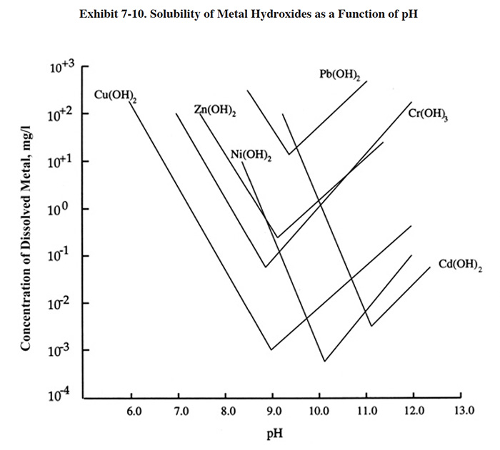
The metals precipitation process begins with pH adjustment, as previously shown in Exhibit 7-1. The pH is usually adjusted to between 8.5 and 10.0, with 9.2 being the most frequent target. The optimal pH for precipitating metals from a wastestream will depend mostly on the species of regulated metals present. Each metal hydroxide has a characteristic solubility that is dependent on pH. Exhibit 7-10 shows the solubility curves for the hydroxides of commonly regulated metals (metal sulfides have different curves with minimum solubilities at much lower concentrations than hydroxides, ref. 348). The lowest point of each curve corresponds to the pH at which that metal species will be removed to its minimum solubility point. For example, copper will be removed to its minimum concentration if the pH of the precipitation step is held at 9.0. Since the low points of the curves occur at different pHs, it is necessary to make a compromise when selecting a target pH (pH control set-point). Often, the pH control set-point selection process is based on the need to reach a low concentration for a particular metal species (e.g., cadmium) that is regulated to a lower concentration than other species.
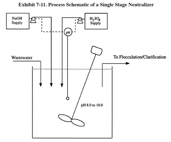
Exhibit 7-11 shows the process schematic of a single-stage neutralizer with provisions for adding both acid and base. Since most combined waste streams are acidic when entering the metals removal step, many facilities do not provide for the addition of acid. However, it is useful in instances when caustic has been inadvertently added in excess and therefore is present in most system designs. With a single-stage system, proportional control for reagent addition is required to maintain a reasonably constant effluent pH. The elevation of the reagent storage and gravity feeding through a proportioning valve is one mode of control. Use of variable speed pumps will achieve the same level of control. If incoming wastes are subjected to wide swings in reagent demand, a two-stage neutralization system should be used. The first stage would control at a pH of approximately 6 to 7 (ref. 39).
Required residence volume in the neutralizer depends on the reagent used. Assuming good mixing, a minimum of 15 minutes residence volume is required for sodium hydroxide; with lime as the alkali, a minimum of 30 minutes is required (ref. 39).
The level of residual dissolved metals after pH adjustment depends on the pH control set-point, the mixture of metals in the wastewater, and whether any compounds are present that interfere with metal hydroxide precipitation.
7.2.4.3 Flocculation
Nearly every metals removal system uses chemical aids to foster particle growth before the wastewater enters the clarifier. By adding coagulating/flocculating agents in slow-mix reactors, the solids in a wastewater can be agglomerated into sturdy, fast-settling particles easily separated in the clarifier. Coagulants/flocculants in broad commercial use include inorganic chemicals such as alum and ferrous sulfate (previously discussed as pretreatments and co-precipitants) and a highly diverse range of organic polyelectrolytes with varying characteristics suitable for different wastewaters. Organic polyelectrolytes are superior to inorganic compounds because both the charge density and valence have been synthetically introduced to the large polymer molecule. The length of the polymer also allows the particles to "knit" together. Normally the appropriate polyelectrolyte is selected by testing a range of different polymers and observing settling behavior after mixing.
7.2.4.4 Clarification
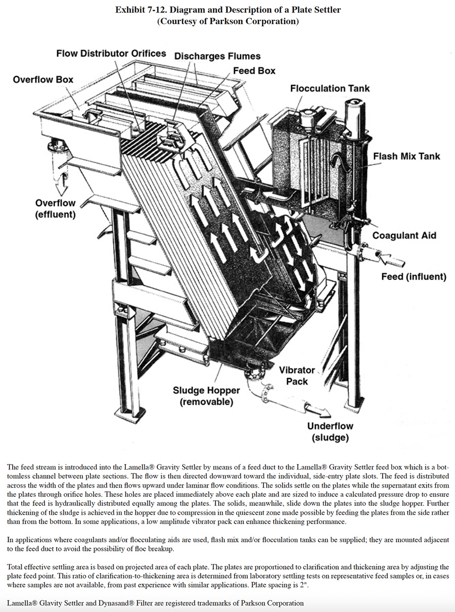
Removal of solids by gravity settling (clarification) is the most common method of separating insoluble particles from a waste stream before discharge. Clarification is a relatively simple process that relies on a density difference between the particles and water and the presence of gravity. However, it is often the unit operation of the waste treatment process most subject to upsets. With effluent limits placing strict control on the level of suspended solids in the wastewater, many modifications to the original circular clarifier have resulted from research and development activities. The two most successful approaches include the sludge blanket clarifier and the plate settler. In the sludge blanket unit, the clarifer inlet first passes through a sludge blanket of agglomerated particles. The mixing tends to promote particle growth and reduce the concentration of slow-settling particle fines. The plate settler (Exhibit 7-12) relies on a series of inclined plates between which the wastewater flows in an upward direction. In essence, the particles must only settle a few inches before impinging on the plate surface. The particles then slide down the plate surface to the base of the separator. In a chamber of equal size, plate settlers can provide considerably greater effective settling volume than a conventional clarifier.
 |
Performance of clarifiers varies significantly depending on the type of waste, the design of upstream components, and the design of the clarifier itself. According to EPA, a "properly operating system" has a total suspended solids (TSS) concentration of 50 mg/l or less and the mean concentration of such systems is 16.8 mg/l TSS (ref. 386). A well-operated clarifier will have, at best, 5 to 10 mg/l of suspended solids in the overflow (ref. 477). Frequently, turbidity in the overflow contributes to the metals content of the discharge and makes strict pollutant guidelines difficult to meet. Consequently, many advanced waste treatment systems employ a polishing filter that uses a sand bed or mixed media filter to remove suspended solids not effectively removed by clarification (ref. 39). Another option is the use of membrane filtration, which either supplements or replaces the clarification step (see Section 7.4.4).
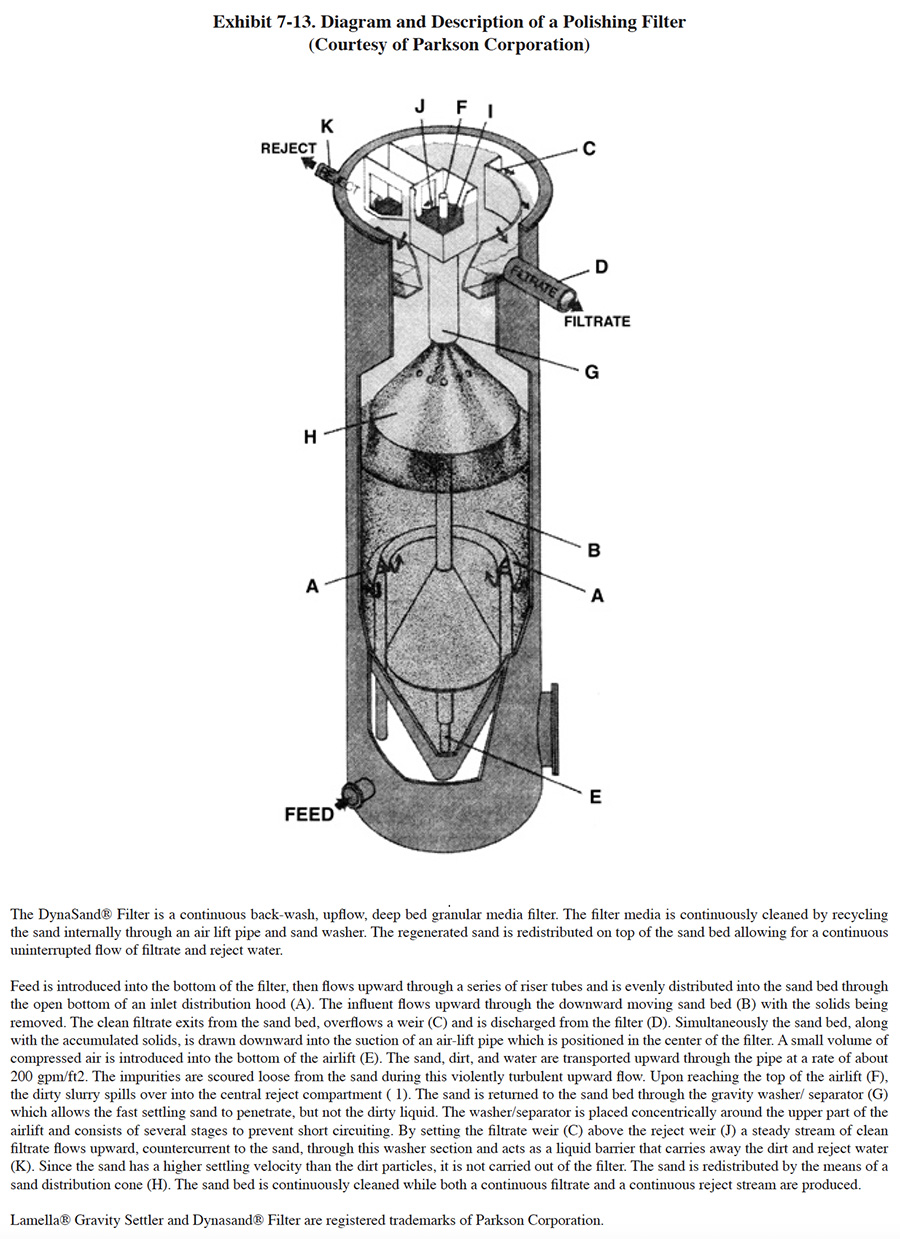
Granular media polishing filters are used for the removal of suspended solids in the 5 to 50 mg/l range where an effluent of less than 1 Jackson Turbidity Unit2 (JTU) is desired (ref. 362). These units typically contain graded sand or multimedia such as garnet, ground anthracite and silica sand. The principal solids removal mechanism of these units is straining. When a single medium such as sand is employed, it will classify in the filtration tank according to size, with the smallest grains at the top. When water flows downward through the sand, which was common with older designs, the solids would form a mat on the surface and filtration only occurred in the top few inches. The sand bed was then cleaned by an upward washing of the bed with water or with water and air (ref. 362). A patented alternative design permits upward feed flow and a continuous backwash of the sand bed as described in Exhibit 7-13.
 |
Multimedia filters employ two or more filter media with different grain size and densities. The media are selected such that the smaller particles are the most dense (e.g., garnet with a specific gravity of 4.5 and particle size of 0.2 to 0.4 mm), the medium-sized particles have an average density (e.g., sand grains with a specific gravity of 2.65 and a grain size of 0.5 mm) and the largest particles are the least dense (e.g., anthracite grains with a specific gravity of 1.6 and a grain size of 1.0 mm). When mixed and permitted to settle, the multimedia bed will grade itself according to the density of the material. Therefore, the smallest particles will locate at the bottom and the largest particles at the top. When the feed stream flows from top to bottom, the courser suspended solids will be removed in the upper layers of the filter and the smaller suspended solids near the bottom. Backwashing is performed in the opposite direction.
The results of the Users Survey indicate that 58 respondents (or 19.3%) employ polishing filters.
Some respondents to the Users Survey use alternative methods of removing metal hydroxides rather than using standard clarification. PS 036 and PS 168 pump the entire volume of treated wastewater containing precipitated metals through a filter press (use of the filter press is normally reserved for settled sludge). Both of these shops have wastewater flow rates below 3,000 gpd, which is the reason they are able to use this method of separation. As indicated by Roy (ref. 38), when direct filtration is used, the gelatinous character and the shear bulk of solids results in premature blinding or blockage of the filter, causing minimal hydraulic throughput. One respondent to the survey uses dissolved air flotation (DAF) rather than settling (PS 240). A DAF unit generates fine air bubbles that attach to the hydroxide particles and cause them to rise to the surface of a tank, where they are removed by skimming. It is a treatment technology commonly used by industries with oily waste-streams (e.g., petroleum refining and industrial laundries). Several shops use membrane filtration to separate precipitated metals. This method of treatment is a viable alternative to conventional clarification for plating shops, but currently is more common to the printed circuit board industry. Microfiltration is discussed in Section 7.5.3.
7.2.4.5 Metals Removal Process Limitations
As a summary for the conventional metals removal subsection, the following limitations of the hydroxide precipitation/clarification process are presented:
- The process cannot precipitate metals to low levels of solubility in the presence of chelating compounds unless additional treatment reagents are employed. The use of additional treatment reagents may significantly add to the volume of sludge generated by the process.
- The precipitation/clarification process cannot remove suspended solids below approximately 5 to 10 mg/l TSS and TSS can range up to 50 mg/l for a well operated system unless polishing filtration is employed. Because the suspended solids remaining in the effluent contain metals, this factor limits the attainable effluent concentration for metals.
• Certain metal hydroxides are amphoteric; that is, solubility is at a minimum at a specified pH and increases if pH is higher or lower. The solubility minimum for different metals occurs at different pH levels (ref. 39). Therefore, a compromise is necessary with mixed metal wastes that limits attainable effluent concentrations.
• The metal hydroxide sludge resulting from treatment of electroplating wastewater has been classified as a hazardous waste (F006) and must be managed, handled, transported, and recovered or disposed of under the provisions of RCRA.
7.2.5 Sludge Dewatering
Dewatering is primarily a physical operation that separates the liquid and solid portions of the dilute sludge generated during the precipitation/clarification process. The resulting material is a stiff fluid. Dewatering is usually performed in a series of steps utilizing two or more pieces of equipment, with each subsequent step reducing the percentage of liquid in the sludge as previously shown in Exhibit 7-1.
In the treatment of metal-bearing wastes, the dewatering process begins once the dilute sludge is removed from the clarifier. The sludge from the clarifier of most precipitation processes will have a solids concentration of 0.5 to 3 percent (ref. 39). Further sludge concentration is first accomplished by the use of thickening equipment which will increase the solids content to between 2 and 5 percent. Sludges are thickened primarily to decrease the capital and operating costs of subsequent sludge processing steps by substantially reducing the volume. There are three general methods of thickening:
- Gravity Thickening
- Flotation Thickening
- Centrifugal Thickening
Gravity thickening is by far the most commonly used method in the metal finishing industry. It can be achieved in a separate tank or within the clarifier, if it is so designed (ref. 331). Thickening within the clarifier is achieved at the lowest part of the clarifier within a sludge storage zone or hopper. Within the hopper, the sludge is slowly mixed with a motorized rack to enhance the release of water. Often, a secondary tank is used to supplement or replace the thickening zone of the clarifier, especially when extended thickening times are required. These units are typically designed to store the accumulated solids for at least 24 hours. Chemicals are sometimes added to aid the thickening process (e.g., iron and aluminum salts, polymers).
The main design variables to be considered in selecting a thickening process are:
- Solids concentration and volumetric flow rate of the feed system
- Chemical demand and cost if chemicals are employed
- Suspended and dissolved solids concentrations and volumetric flow rate of the clarified stream
- Solids concentration and volumetric flow rate of the thickened sludge.
Other variables that impact the selection of a thickening process are: subsequent processing steps; operation and maintenance (O/M) cost; and the reliability required to meet successful operational requirements. Detailed selection, design and operating parameters for thickening devices can be found in the literature (e.g., ref. 331).
After thickening, further dewatering of the sludge is achieved through the use of mechanical dewatering and thermal dehydration devices. The most widely used mechanical dewatering device is the filter press. Other technologies employed in the metal finishing industry include vacuum filters (used by only two respondents), centrifuges and belt presses (latter two not presently used by any of the respondents). Mechanical dewatering will produce a sludge with an approximately 10 to 60 percent solids content. Sludge dryers (Section 7.2.6) are used to further remove moisture from the sludge and are capable of producing a material with a 90 percent solids content. Increasing the solids content of the sludge greatly reduces its volume, which in turn reduces transportation costs and often disposal/recovery costs. The following discussion focuses on the filter press.
The filter press has a number of advantages over other filtration equipment such as vacuum filters and centrifuges. Filter presses can operate well at variable or low feed solids conditions. They can also produce a relatively dry cake because of the high pressure differential they can exert on the sludge. A typical filter press operating at 100 psig will produce a sludge with a solids content of 25 to 60 percent solids, depending on the chemicals used for precipitation. As a comparison, the basket centrifuge produces a sludge with a solids content of 10 to 25 percent and the vacuum filter produces a sludge with 15 to 40 percent solids (ref. 395).
The disadvantages of the filter press include its batch operating cycle, the labor associated with removing the cakes from the press, and the downtime associated with finding and replacing worn or damaged filter cloths.
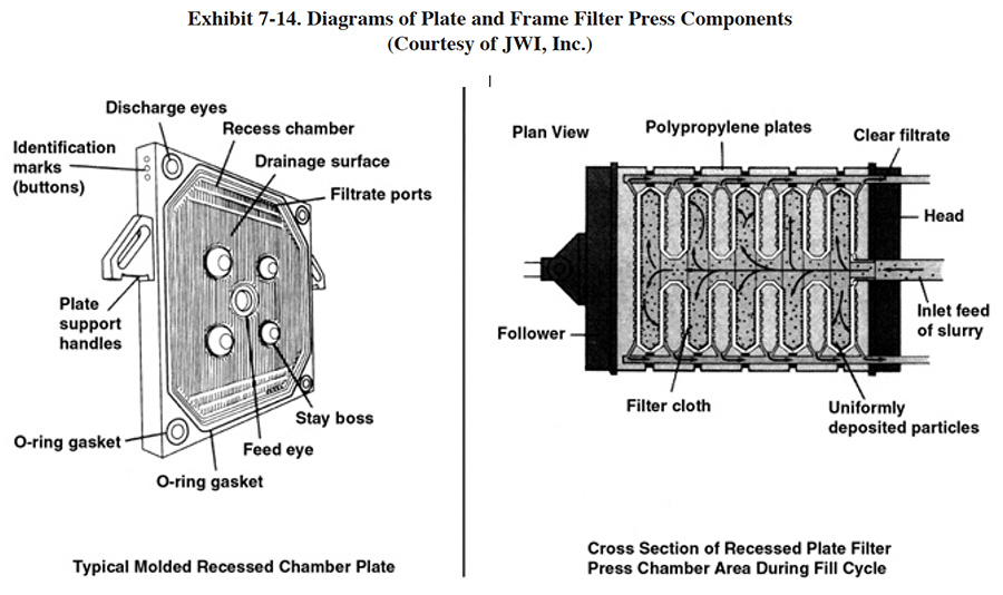
The original filter press design consisted of alternating plates and frames and these types of units were referred to as the plate-and-frame filter press. The modern technology is the recessed plate filter press (see Exhibit 7-14). The plates (usually constructed of polypropylene) are recessed on each side to form cavities and they are covered with a filter cloth. The two types of presses work in basically the same manner. At the start of a cycle, a hydraulic pump clamps the plates tightly together and a feed pump forces a dilute sludge slurry into the cavities of the plates. The liquid (filtrate) escapes through the filter cloth and grooves molded into the plates and is transported by the pressure of the feed pump to a discharge port. The solids are retained by the cloth and remain in the cavities. This process continues until the cavities are packed with sludge solids. The hydraulic pressure is then released and the plates are separated. The sludge solids or cake is loosened from the cavities and falls into a hopper or drum.
 |
Under normal to ideal conditions, a filter press subjected to a 100 psi pumping pressure will produce a cake with a dryness of approximately 25 to 40 percent solids for caustic soda precipitated metal hydroxides and 35 to 60 percent solids for lime precipitated hydroxides (ref. 410). The level of dryness attained depends heavily on the length of the drying cycle. Altmayer suggests that most shops only achieve 20 to 25% dry solids and that to reach higher dryness levels requires a sludge dehydration unit (see Section 7.2.6) (ref. 482).
Modern recessed plate filter presses can be specified with the following design enhancements (ref. JWI file):
- Lightweight polypropylene plates that exhibit good chemical resistance and provide a long service life.
- Gasketed plates that reduce leakage during the filtration cycle. These replace non-gasketed types where the filter cloth extends beyond the plate to form the seal between plates.
- An air blow-down manifold that is employed at the end of the filtration cycle to drain remaining liquid in the system, thereby improving sludge dryness and aiding in the release of the cake.
- Microprocessor control which permits unattended operation throughout the filtration cycle. Capable of automatically adjusting the feed pressure and deactivating the pump whenever hydraulic pressure falls below preset limits.
- Manual, semi-automatic or automatic plate shifters that are used to separate the plates prior to releasing the sludge cake.
Filter presses are available in a very wide range of capacities. Respondents to the Vendors Survey sell equipment with a capacity range of 0.6 ft3 to 200 ft3. A typical operating cycle is from 4 to 8 hr, depending on the dewatering characteristics of the sludge. Units are usually sized based on one or two cycles per day.
7.2.6 Sludge Dehydration
The solids content of the sludge dewatered on a filter press is usually in the range of 25 to 60 percent. This represents an approximately 20 to 1 volume reduction from the original sludge volume discharged from the clarifier/thickener. Additional dewatering can be accomplished with sludge dehydration equipment that can produce a waste material with a solids content of approximately 90%. This represents an approximately 4 to 1 waste volume reduction above that achieved by the filter press. Sludge dehydration equipment is available in both batch and continuous operating modes. Batch units are typically designed with a heated sludge chamber with rotating blades that consistently break up and blend the sludge cake, thereby exposing it to the heat source. Continuous units have a feed hopper and employ an auger or conveyor system that moves a thin layer of sludge through a drying region and discharges it into a hopper. Some continuous units can be located such that the sludge cake discharge from a filter press drops into the feed hopper of the dehydration unit, making the overall dewatering process more automated. System capacities range from less than 1 ft3/hr to more than 20 ft3/hr of feed. Various heat sources are used for sludge drying, including: electric, electric infrared, steam and gas. Energy requirements are mostly dependent on the water content of the feed stock and the efficiency of a given unit. Sludge dehydration equipment will require an air exhaust system.
During the past five years, sludge dehydration equipment has been one of the most frequently purchased of all pollution prevention and control devices.
7.2.7 Sludge Generation and Disposal Data from the Users Survey
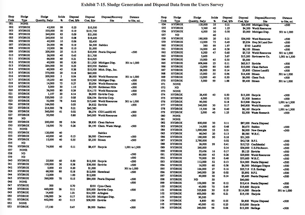
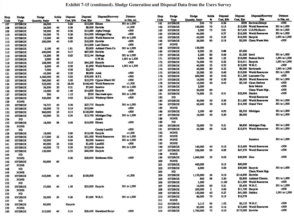
A summary of sludge generation data from the Users Survey is presented in Exhibit 7-15. Column 1 indicates the plating shop code. Column 2 indicates the type of sludge that is generated (e.g., hydroxide, sulfide). In all cases, shops either generated a hydroxide treatment sludge or no sludge (zero discharge shops and shops that do not plate regulated metals). Examples of the latter case are sulfuric acid anodizing shops that simply adjust the pH of the wastewater and discharge it (e.g., PS 001 and PS 037). The average sludge generation rate for all respondents that reported a sludge quantity is 158,272 lb/yr. Column 4 shows the percent solids of the sludge. The average percent solids for all shops was 54%. Columns 5 and 6 show the unit cost and total annual cost of sludge disposal or recovery for each shop (includes transportation, stabilization, disposal/processing and disposal tax). Columns 7 and 8 show the disposal/recovery site name and the distance between the shop and the site. The average and median distances to disposal/recovery sites are 457 and 300 miles, respectively. On the average, recovery sites are further away from shops than disposal sites. For disposal sites alone, the average and median distance to the sites are 330 and 200 miles, respectively. Additional details on recovery sites are presented in Section 8.
 |
 |
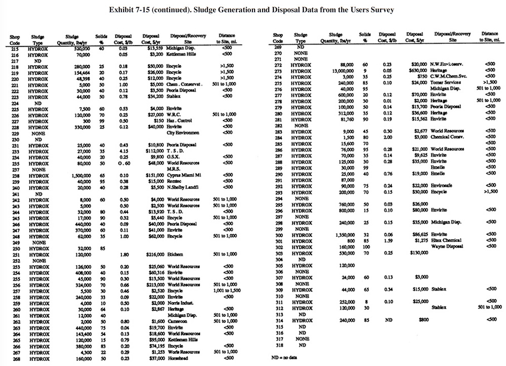 |
The average unit cost for sludge disposal was $0.53/lb and the median cost was $0.25/lb. Unit disposal costs for shops varied, depending mostly on the quantity of sludge generated. The following range of average unit costs were given for various annual sludge generation rates:
lbs/Yr of Sludge Unit Cost $/lb <10,000 $1.34 10,001 to 50,000 $0.51 50,001 to 100,000 $0.43 100,001 to 250,000 $0.25 250,001 to 500,000 $0.22 500,001 to 1,000,000 $0.05
 |
 |
 |
Data showing the chemical constituents of sludges generated by some survey respondents are presented in Section 8 (see Exhibit 8-5).
The following methodology can be used to estimate the sludge generation rate for a particular plating shop. It is based on a model presented in reference 392 that was revised, based on the chemical constituent data collected during the Users Survey (see Exhibit 8-5).
Sludge Generation:
(1) Calculate lbs/yr of dry sludge solids:
First, for each metal in the wastewater, multiply the lbs/yr of metal precipitated (this value can be assumed to be equal to the mass of metal in the influent) by its "solids generation factor," and sum.
Metal Solids Generation Factor Cr 1.98 Ni 1.58 Cu 1.53 Cd 1.30 Fe 1.61 Zn 1.52 Al 2.89 Other* 1.77 (avg.)
*see Exhibit 8-5 in Section 8 for identification of "other" metals contained in plating sludges.
(1a) If the sludge will be dewatered above 50% solids, multiple by:
[(0.029 x % Solids*) - 0.41]
(1b) The "solids generation factors" are based on the use of caustic as an alkali reagent. If lime will be used instead of caustic, multiply by 1.13.
(2) Lbs/yr of wet sludge = 100 (lbs dry solids/% Solids*)
*express as a whole number, e.g., 50% = 50
7.3 COSTS OF CONVENTIONAL WASTEWATER TREATMENT
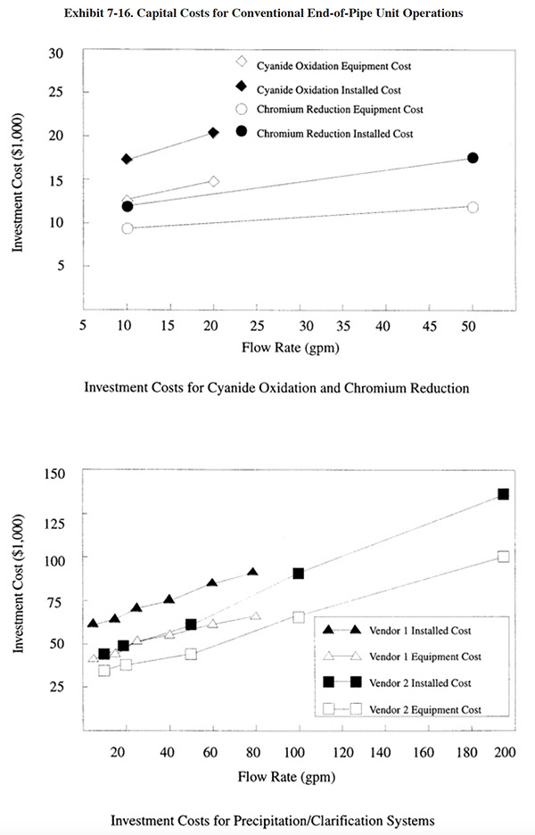
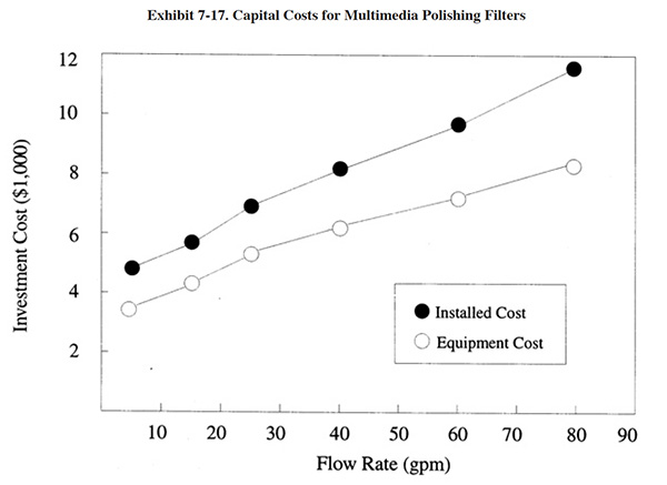
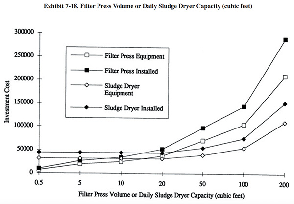
7.3.1 Capital Costs
Capital costs for conventional end-of-pipe treatment equipment are presented in Exhibits 7-16, 7-17 and 7-18. For each unit operation, both basic equipment costs and installed equipment costs are presented. Installation costs (38% over basic equipment costs) include: engineering (10%), shipping (5%), piping (8%) and electrical/instrumentation (15%). All equipment costs are for packaged, skid mounted systems. The unit operations are based on the following retention times:
• cyanide oxidation first stage: 60 minutes
• cyanide oxidation second stage: 120 minutes
• chromium reduction: 30 minutes
• neutralization: 30 minutes
• precipitation: 30 minutes
• sludge thickening: 24 hours
• polishing filter: 10 minutes
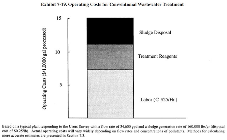
7.3.2 Operating Costs
The major operating cost items for conventional treatment (labor, treatment reagents and sludge disposal) are shown in Exhibit 7-19. This chart is based on the results from the NCMS/NAMF Users Survey, which are discussed in Section 7.4. An individual shop can use the results of the survey and other data presented in this text to accurately estimate their chemical treatment reagent costs, based on the individual wastestream (i.e., Cr, CN, acid/alkaline) flow rates and characteristics.
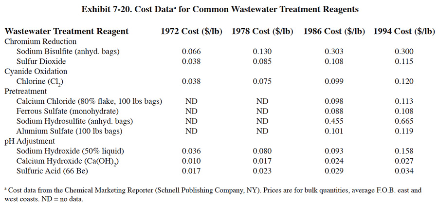
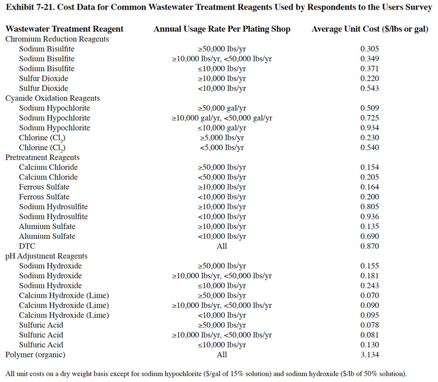
Treatment reagent prices have risen dramatically over the past 20 years due to inflation and increased manufacturing costs (Exhibit 7-20). During this time period, most reagent costs have increased by a factor of two to five times. The actual reagent unit costs paid by respondents is significantly impacted by the annual quantity of reagent that is purchased. This is due to the packaging costs for small quantities vs the lack of packaging for bulk quantities. Exhibit 7-21 presents average treatment reagent prices paid by respondents, based on usage rates.
 |
 |
 |
The quantity of reagents used by respondents was somewhat unexpected. As discussed in Section 7.4, on the average, respondents use much greater amounts of reagents than needed to satisfy chemical equations governing the treatment process reactions (i.e., stoichiometric requirements). This effect is due to several factors (based on conversations with survey respondents): (1) wastewaters contain buffering, chelating and other types of substances that interfere with the treatment processes and cause higher than expected reagent requirements; (2) wastestreams can be highly variable both in terms of flow and pollutant concentration, which causes dramatic swings in chemical feed and results in some wasted reagent; (3) shops must meet effluent regulations 100% of the time, rather than be in compliance "on the average," which causes them to add excess reagents; (4) local effluent requirements for cyanide or a particular metal species are often below the Federal limitations and can only be met by overdosing the wastewater with reagents; (5) treatment system designs may not be ideal; (6) instruments (e.g., ORP and pH) and chemical feed systems may not function perfectly all the time; and (7) operator ignorance or error.
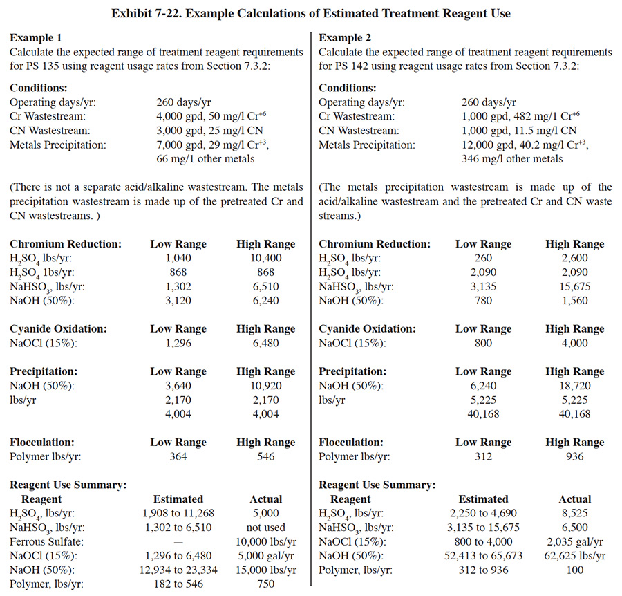
The following are typical ranges of treatment reagent usage rates for survey respondents for each of the steps in the conventional treatment process3. Examples of calculations using these factors are presented in Exhibit 7-22.
 |
Chromium Reduction
H2SO4: 1 to 10 lbs/1,000 gal, and 2 lbs/lb Cr+6
NaHSO3: 3 to 15 lbs/lb Cr+6, or
SO2: 2 to 10 lbs/lb Cr+6
NaOH (50%): 3 to 6 lbs/1,000 galCyanide Oxidation
NaOCl (15%): 8 to 40 gal/lb CN
Precipitation
NaOH (50%): 2 to 6 lbs/1,000 gal, and
5 lbs/lb Cr, and
4 lbs/lb other metalsFlocculation
Polymer: 0.1 to 0.3 lb/1,000 gal
 |
 |
 |
7.4 END-OF-PIPE TREATMENT SYSTEM DATA FROM THE USERS SURVEY
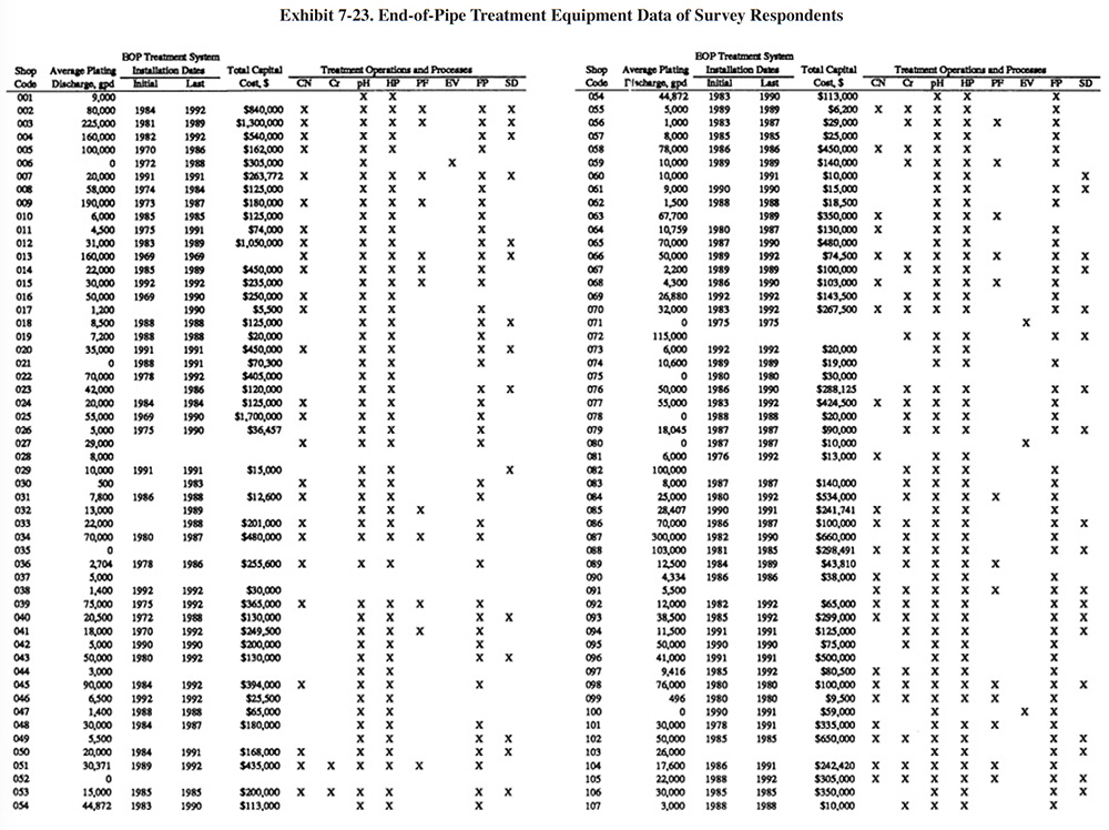
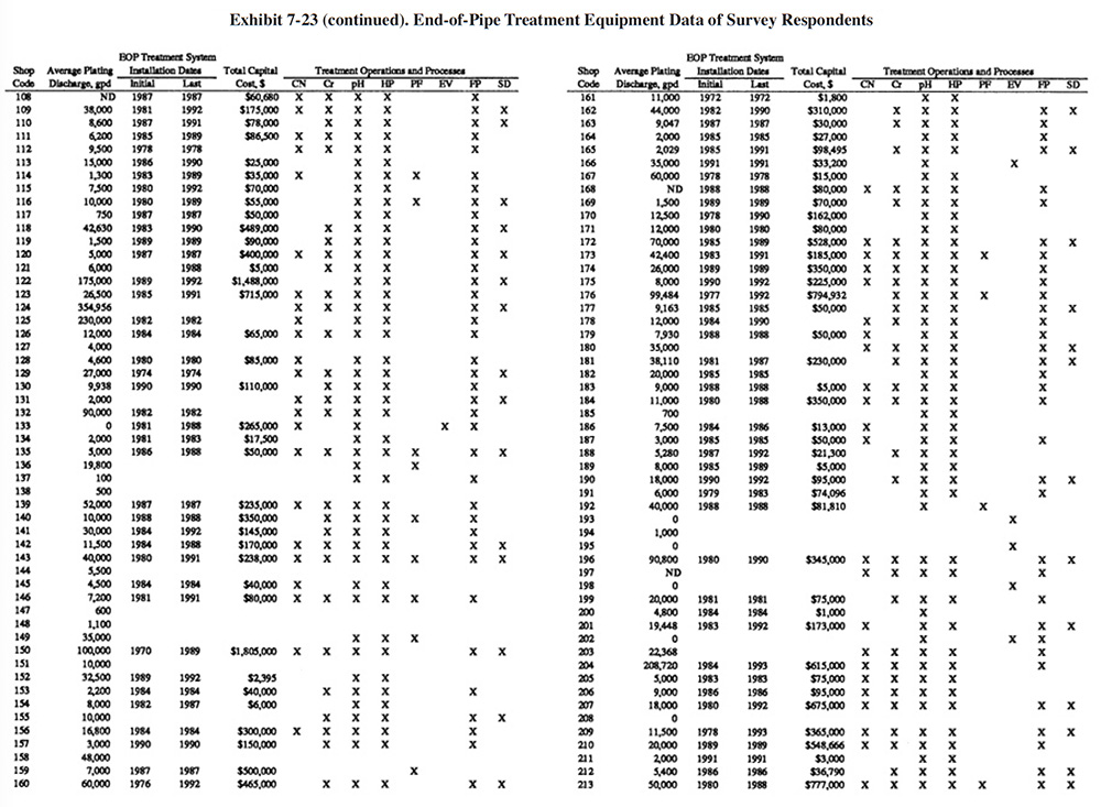
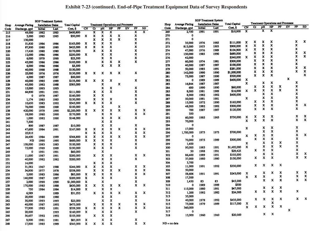
Exhibit 7-23 presents a summary of the end-of-pipe (EOP) treatment equipment purchased by the survey respondents. Most respondents purchased their EOP equipment in stages. Exhibit 7-23 shows the initial and final purchase dates (years) of equipment and the total capital cost of all equipment purchased. Also shown in Exhibit 7-23 are the types of treatment operations and processes that are present. Appendix B presents further details on these equipment purchases including the manufacturer of each major equipment item purchased (includes information on the initial system and up to three system additions), its cost and the shop's satisfaction level (shops were asked to rate on a scale of 1 to 5 their level of satisfaction with the equipment with 1 being the lowest satisfaction level and 5 being the highest).
For plating shops reporting treatment system costs, the average cost was $252,141 (purchased between 1967 and 1993). The following indicates the percentage of shops that reported the purchase of each type of unit operation:
- CN Cyanide Destruction 44.7%
- Cr Chromium Reduction 58.3%
- pH pH Adjustment 90.0%
- HP Hydroxide Precipitation 85.7%
- SP Sulfide Precipitation 0.0%
- PF Polishing Filter 19.3%
- EV Evaporation 3.7%
- FP Filter Press 75.0%
- SD SludgeDryer 29.3%
- Oth Other (e.g., ion exchange) 2.7%
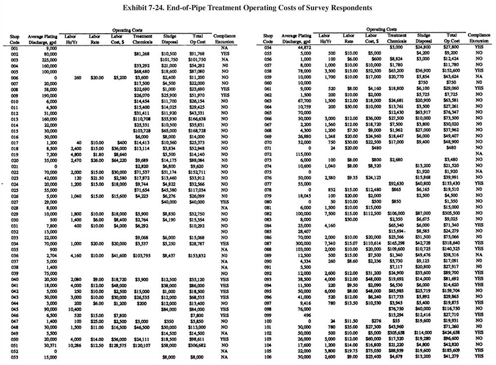
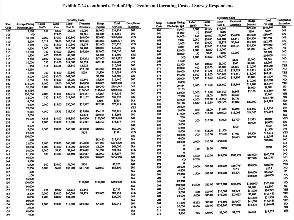
Exhibit 7-24 presents a summary of operating data submitted by the respondnents. Columns 1 and 2 show the shop code and the average electroplating wastewater flow rate. Columns 3, 4 and 5 provide treatment system labor information. Shown are the number of annual hours spent for system operation and maintenance, the hourly rate paid to the operators (in some cases the shops provided loaded rates that included overhead) and the total dollars spent annually for labor. Columns 6 and 7 show the annual costs for treatment chemicals and sludge disposal, and column 8 shows the sum of the reported annual operating costs (labor, treatment chemicals and sludge disposal). The final column indicates if a shop reported a compliance excursion ("Yes") or not ("No") or did not answer ("NA") that question on their survey form.
 |
 |
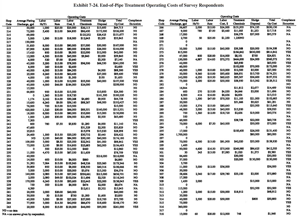 |
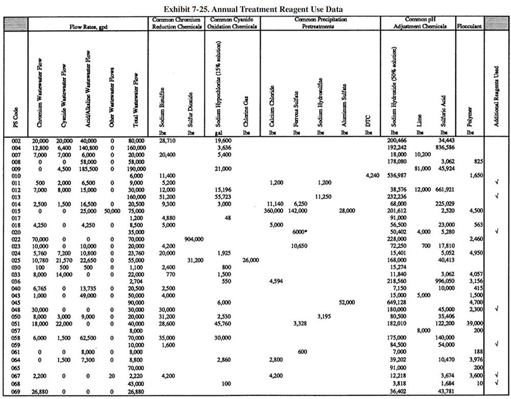
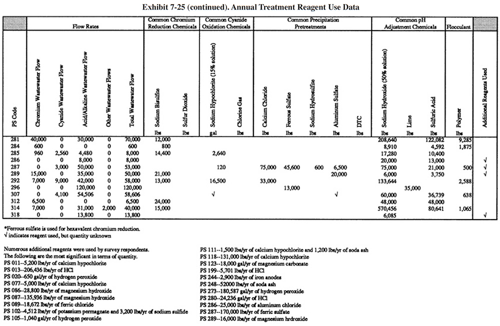
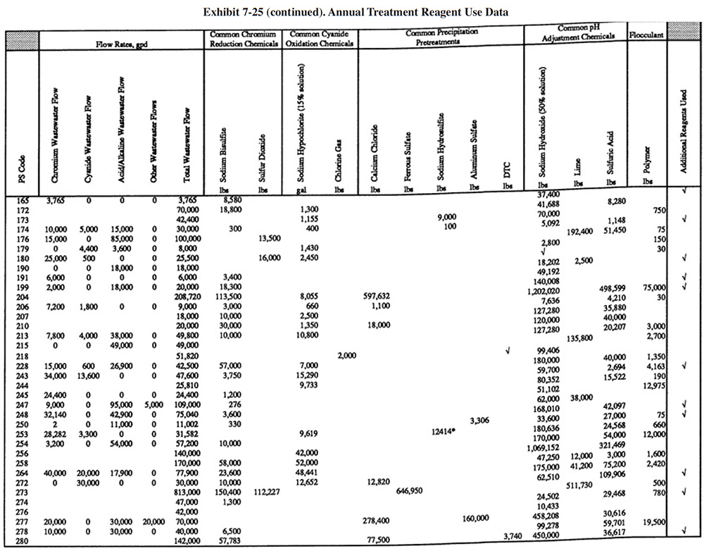
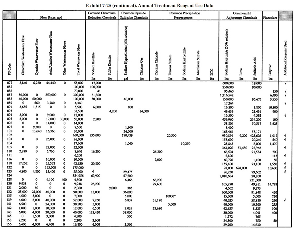
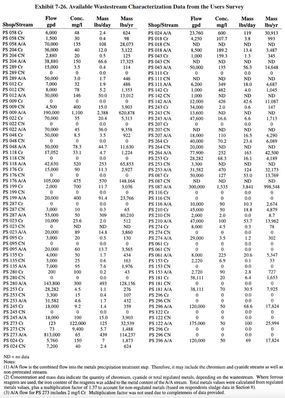
Exhibit 7-25 presents the chemical use data for survey respondents (not all shops were able to submit these data). Available wastestream characterization data for these shops are presented in Exhibit 7-26 (even fewer of the shops had characterization data). These data were used in developing the reagent use formulas in Section 7.3.2. As previously discussed, the data in Exhibits 7-25 and 7-26 indicate that actual reagent use is significantly higher than theoretical use. This is especially true for sulfuric acid. Higher than expected sulfuric acid usage rates are most common during the pH adjustment step in the chromium reduction process. This is most likely due to the buffering capacity of the wastestreams, which is not accounted for in commonly accepted models.
 |
 |
 |
 |
 |
7.5 ALTERNATIVE TECHNOLOGIES FOR METALS REMOVAL
7.5.1 Overview
For many plating shops, the conventional hydroxide precipitation/clarification process will be the most economical and reliable end-of-pipe method of meeting metals discharge limitations. However, for various reasons, shops may want to employ an alternative metals removal process. Some of the more common reasons include:
- Some local jurisdictions have adopted discharge standards more stringent than the Federal regulations. Because the Federal regulations are based on the technical capabilities of conventional treatment, these processes are often unable to achieve the lower concentration limits.
- Metal finishing wastewaters often contain compounds that interact with dissolved metals and interfere with their precipitation as metal hydroxides. Such compounds as ammonia, phosphates, tartrates, and ethylene-diaminetetraacetic acid (EDTA) are commonly used in plating and printed circuit board operations and consequently find their way into the wastewater. These compounds, called chelates, combine with the dissolved metal ion to form a complexed ion that is relatively soluble in neutral or slightly alkaline solutions. In many cases, waste streams containing high levels of chelates (e.g., printed circuit board shops) cannot be treated with conventional precipitation to the level required by Federal regulations.
- In some cases, metal discharge requirements are not being met, even though the level of dissolved metals in the effluent is low. In cases of this kind, the solids separation component of the process may be allowing too much suspended matter, including precipitated metals, to pass into the discharge. This condition can result from overloaded or poorly designed clarifiers, ineffective conditioning (coagulation or flocculation) of the clarifier feed, or poor pH control.
- Some shops may find that the capital and/or operating costs of conventional processes are too high. Alternative technologies may reduce capital costs under certain conditions (e.g., if a centralized waste treatment plant is located nearby) and/or specific components of operating costs (e.g., shops located long distances from sludge disposal sites may focus on reducing sludge volumes).
The alternative technologies discussed in this section are the ones that have been installed by the respondents to the Users Survey; they include: ion exchange, microfiltration and evaporation. Each of these alternatives offers solutions to one or more of the technical problems encountered with conventional treatment or, in some cases, offers cost savings through a reduction in equipment requirements or operating expenses such as chemical reagent purchases. In all cases, however, alternative technologies offer a trade-off. Their advantages are gained at the expense of other benefits. Such trade-offs are often site-specific and must be evaluated case by case.
In addition to the three alternative technologies for metals removal discussed in this report, there exists many other alternatives that have been reported in the literature and/or utilized in plating shops. Examples of these include sulfide precipitation, sodium borohydride precipitation, dissolved air flotation, freeze crystallization, and insoluble starch xanthate treatment. Of these technologies, sulfide precipitation is the most widely applied in the metal finishing industry. Although it is not used by any respondents to the Users Survey, it is used in the plating industry, as documented in the literature (e.g., ref. 39, 393, 348). Also, the sulfide precipitation chemistry is sometimes used with end-of-pipe membrane filtration systems. This application is discussed in Section 7.5.3.
7.5.2 Ion Exchange
7.5.2.1 Overview
This section deals with ion exchange as an end-of-pipe technology. Ion exchange is a versatile pollution prevention and control tool for the metal finisher. It is utilized for raw water treatment, metals recovery, water recycle, bath maintenance and end-of-pipe treatment. Use of ion exchange for metals recovery/water recycle and process solution maintenance are discussed in Sections 4 and 5, respectively.
Approximately 6% of the respondents to the Users Survey use ion exchange as an end-of-pipe technology. Several different configurations are being employed by survey respondents and these are discussed in Section 7.5.2.3.
A general description of the ion exchange process is presented in Section 4.
7.5.2.2 Development and Commercialization
The development and commercialization of the ion exchange technology is discussed in Section 4. No direct references were found in the literature to indicate when ion exchange was first applied as an end-of-pipe technology. However, it can be assumed from the fully developed nature of the technology and the need to meet local discharge standards in certain locations of the U.S. that the technology was applied for this purpose in the 1950's. The earliest application from the Users Survey was 1972 (PS 161). The EPA's regulatory document for the metal finishing industry indicated that 63 of the plants in their database used ion exchange (ref. 386). Their data collection efforts were performed in the late 1970's and early 1980's. The EPA document is unclear as to the total number of plants included in the database and therefore the percentage of shops that used ion exchange at that time cannot be calculated. However, as a comparison, EPA indicated that 154 of the plants in their database used hydroxide precipitation, a very common end-of-pipe technology. This would indicate that ion exchange had a very prominent role in pollution control at the time of the EPA study. (Note that a portion of the ion exchange users in the EPA report may have used the technology for raw water treatment, metals recovery or bath maintenance. EPA does not specify which applications were used by the shops in their database.)
Ion exchange is a very important end-of-pipe technology for shops utilizing the services of a centralized waste treatment (CWT) facility. Ion exchange resin beds can be shipped to a CWT facility more economically and safely than liquid wastes. CWT systems that utilized ion exchange were present in Europe and Asia in the 1970's (ref. 387). Small U.S. operations were present in the 1970's; however, the only major U.S. CWT plant (Minnesota Recovery Systems) was not operating until 1988 (ref. 419 ).
The Users Survey indicates that the role of ion exchange as an end-of-pipe treatment technology has continued through the 1980's and into the 1990's. Several shops have installed end-of-pipe equipment after 1990. Also, several of the respondents are using CWT services for regeneration of the columns, including four shops using the new CWT plant in Minnesota.
7.5.2.3 Applications and Restrictions
The shops that are discussed in this section use ion exchange for treatment of a mixed metal waste stream and/or they use it as the sole end-of-pipe method of meeting effluent limitations for metals.
In some cases, it is difficult to differentiate between recovery and end-of-pipe treatment applications of ion exchange and therefore several shops are discussed in both Section 4 and this section. These are shops that treat a single metal wastestream using ion exchange, but do not recover the metals on-site. Rather than recovering the metals on-site, these shops use a centralized waste treatment system for regeneration or they regenerate on-site and send the regenerant to an off-site metals recovery facility. In either case, their ion exchange system is the sole means of metals removal from their wastewater (i.e., no conventional treatment is present). Shops that fall into this category include: PS 061, PS 161, PS 136, PS 192, and PS 196.
Some shops in the Users Survey that employ ion exchange without any chemical recovery were placed solely into the recovery category (i.e., Section 4.4). This is a group of shops that does not perform chemical recovery; however, they treat a single metal rinse water using ion exchange, and therefore there exists a high potential for recovery. Also, each shop in this group has another technology present for end-of-pipe treatment (e.g., hydroxide precipitation). Because ion exchange is not used as their primary treatment system, this group of shops is only included in Section 4. As a result of this grouping, readers interested in ion exchange treatment should review both sections to benefit fully from the results of the Users Survey.
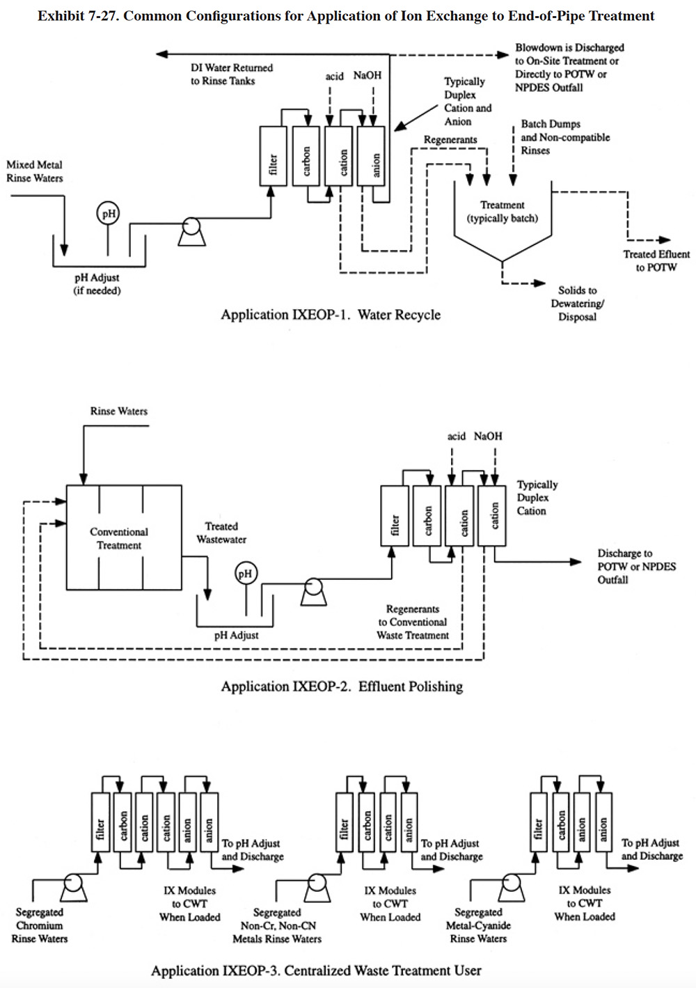 |
Ion exchange is employed as an end-of-pipe technology using three common schemes, as depicted in Exhibit 7-27. Variations of these three configurations were also observed. The first configuration employs ion exchange to remove the metals from large volumes of miscellaneous wastewaters and concentrate them into a smaller volume for subsequent treatment by conventional means (see application IXEOP-1). This was the most frequently used method of end-of-pipe ion exchange treatment by respondents to the Users Survey (PS 021, PS 036, PS 089, PS 121, PS 170, PS 187, PS 200, PS 221, PS 223, PS 209). This strategy reduces the capacity requirement of the conventional system and therefore may result in capital savings. With this configuration, all dilute rinses are sent to integrated ion exchange units (see definition in Section 4). The number of units needed will depend on the flow rate and the mixture of pollutant parameters present. As with conventional treatment, segregation of cyanide, chromium bearing and miscellaneous metal bearing rinse waters is needed. Pretreatment of the rinses may include one or more of the following processes: pH adjustment, cyanide destruction, filtration and carbon treatment. The pH adjustment step, which was performed by most shops using this configuration, is needed to ensure that the pH is within the operating range of the resin. Cyanide destruction, which was used by only one of the survey respondents (PS 223), will reduce the number of steps of the ion exchange process when cyanide complexes are present (see Section 4, Section 4.4.3 for a discussion of ion exchange treatment of cyanide-metal wastewaters). Filtration and carbon treatment, which are the most common pretreatment technologies, are needed to remove suspended solids and organics that may foul the resin beds. If water recycle is desired, the ion exchange system must consist of both anion and cation columns. Cation only systems can be used if water recycle is not desired and there are no chromates or cyanide present (these two pollutants are removed by anion resins). Concentrated wastes generated in the plating shop (e.g., batch dumps), should be discharged directly to the batch treatment system, rather than into the ion exchange feed stream. This practice prevents overloading of the ion exchange beds. Also, it should be noted that ion exchange is simply not a good technology for the treatment of concentrated wastes. If used for this purpose, the regenerant may be less concentrated than the original waste.
From the Users Survey, 11 respondents (or 3.5% of all respondents) utilized application IXEOP-1 for treatment of mixed metals waste streams. Of these, 7 shops recycle the water treated by ion exchange to rinse tanks (PS 021, PS 036, PS 170, PS 185, PS 187, PS 200, PS 209) and 4 shops do not recycle water, but rather discharge it directly to a sewer (sometimes after pH adjustment) or further process it with additional metals removal treatment (e.g., hydroxide precipitation) and then discharge it (PS 089, PS 121, PS 221, PS 223).
Shops that employed application IXEOP-1 with water recycle generally had a lower than average discharge rate. The average for all shops in the survey (318 shops) was 34,600 gpd and the average for the 11 shops using application IXEOP-1 was 10,064 gpd. One the shops using ion exchange for water recycle attained zero-discharge of effluent (PS 021). This shop batch treats regenerant in a 1,500 gallon tank (chromium reduction and metals precipitation), transfers the liquid waste to an atmospheric evaporator for concentration and dewaters the concentrate and sludge with a filter press. Approximately 1,100 lbs of sludge (20% solids) is sent off-site per year.
In the second configuration (application IXEOP-2), ion exchange is used as a polishing technology to remove residual pollutants following conventional treatment. Such applications are most common to facilities that directly discharge wastewaters to rivers or streams and are required to meet stringent metals limitations (ref. 39). Respondents to the Vendors Survey indicated that they have installed 21 polishing systems. However, only one Users Survey respondent used ion exchange in this manner (PS 068). The regulations for this particular plating and anodizing shop are below the 40 CFR 433 limitations for most parameters. PS 068 does not regenerate their spent resins on-site. Rather, they send them off-site for incineration and metals recovery, which is an unusual practice for this ion exchange application, especially considering the moderately high cost of resin. Their spent resins contain nickel, copper, silver and zinc. Presumably, the quantity of silver present in their resins justifies this practice.
IXEOP-2 is not a good configuration to use for recycling water. Water recycling requires the use of both anion and cation columns (i.e., deionization). Because the wastewater treatment process adds such an abundance of sulfates and chlorides to the wastewater, it is economically impractical (except under unusual conditions) to recycle it using ion exchange. The loading on the anion column and the resultant regeneration frequency would simply be too great. If water recycle is the goal, it is better to segregate wastewaters and recover the water as shown in application IXEOP-1 (ref. NAPCO file).
Ion exchange polishing applications generally use metal selective cation resins that have a high preference for heavy metal cations over the more common alkali or alkaline earth cations such as sodium, calcium, magnesium and potassium that are added by the conventional treatment process.
In the third configuration (application IXEOP-3), ion exchange is used as the primary end-of-pipe treatment for segregated metal and cyanide bearing rinse waters and the resin columns are sent to a CWT facility for regeneration. Because the wastestreams were segregated before ion exchange, the regenerants contain metals that can be recovered by relatively easy means (e.g., electrowinning). Application IXEOP-3 is based on sketches submitted by PS 192 and PS 237. Other shops using CWT had similar configurations (PS 136, PS 249), with only one significant variation, where resins were regenerated on-site and the regenerant was sent to an off-site metals recovery firm.
7.5.2.4 Technology/Equipment Description
This subsection contains a description of commercially available ion exchange equipment that is manufactured and/or sold by vendor survey respondents. This is intended to provide the reader with information and data on a cross section of available equipment. Mention of trade names or commercial products is not intended to constitute endorsement for use.
Descriptions of ion exchange system designs and commercially available equipment are presented in Section 4.4.4. Systems for applications IXEOP-1 and -2 will typically be integrated units and modular units are used for IXEOP-3. One additional commercial system is described in this section that is advertised specifically as end-of-pipe treatment. It would be employed as shown in Exhibit 7-27, application IXEOP-1.
Memtek Corporation manufactures the Rinse Water Maintenance System (RMS™), which is advertised as an end-of-pipe treatment/water recycle system. The unit has duplex cation and anion beds, employed in a parallel/standby mode of operation (see Section 4, Section 4.4.1.3 for definitions). It is advertised to be applicable to chromium, cyanide and acid/alkaline rinse waters. Optional equipment includes a batch treatment system for regenerants as well as an atmospheric evaporator or electrowinning unit for further processing the regenerants.
7.5.2.5 Costs
7.5.2.5.1 Capital Costs
Capital costs for end-of-pipe ion exchange equipment will be similar to those presented in Section 4, Section 4.4.5.1 for integrated and modular systems.
7.5.2.5.2 Operating Costs
Operating costs for end-of-pipe ion exchange equipment will be similar to those presented in Section 4.4.5.2 for integrated and modular systems. End-of-pipe applications may experience higher resin costs (approximately 25%) due to a shorter life span and higher fines loss (ref. Kinetic Recovery Corporation file).
Several respondents to the Users Survey provided operating cost data for using a CWT service (PS 161, PS 192, PS 237). The following data were provided by these respondents.
PS 161 leased their ion exchange columns that contain 3.2 ft3 of mixed (anion and cation) resin. During 1992 PS 161 sent 18 nickel columns and 8 chromium columns to Dayton Water Systems. The cost of the service was $336 per column ($105/ft3) for regeneration plus a $70 per month rental fee for the equipment (therefore, the total annual cost for 1992 is $6,888 for nickel and $3,528 for chromium). According to the respondent, Dayton Water Systems sent the regenerant to Inmetco for recovery of the metal (see Section 8 for information on off-site recycling).
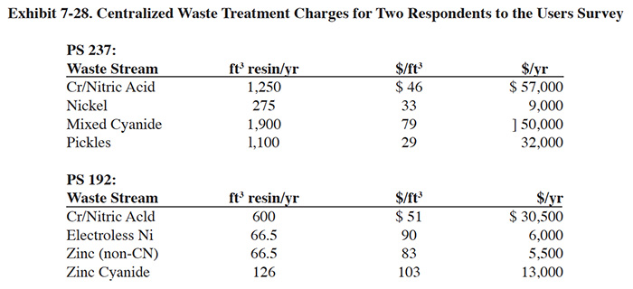 |
PS 192 and PS 237 use the Metropolitan Recovery Systems CWT facility in Minnesota. Their operating costs are shown in Exhibit 7-28.
7.5.2.6 Performance Experience
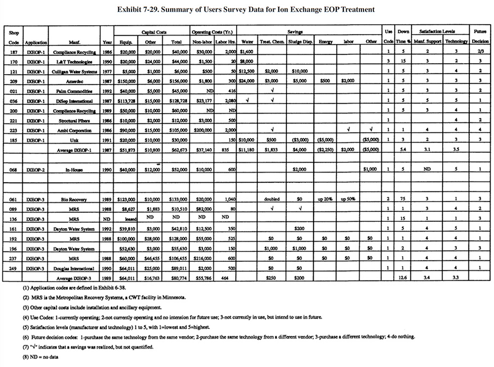
Different sections and questions were contained in the Users Survey form for recovery (Section 6 of the survey form) and end-of-pipe systems (Section 7 of the survey form). Although respondents that use ion exchange for end-of-pipe were not asked to complete Section 6 for these applications, all of them did. Therefore, there are more data available for ion exchange end-of-pipe applications than for than for most other end-of-pipe applications. A summary of the data for ion exchange applied to endof-pipe treatment is presented in Exhibit 7-29.
 |
The following information and data summarize the perfonnance experience of the survey respondents.
- The performance of ion exchange, as an end-of-pipe treatment technology, was rated approximately the same as for recovery applications. The average satisfaction level for ion exchange applied to end-of-pipe treatment is 3.5 for IXEOP- 1, 5.0 for IXEOP-2 (only one respondent) and 3.4 for IXEOP-3, whereas the average level rating for ion exchange used for chemical recovery is 3.5. Fourteen of the shops (or 74 %) indicated that this technology satisfied the need for which it was purchased (includes all applications), 4 (or 21%) indicated that it partially satisfied the need for which it was purchased and 1 (or 5%) indicated that it did not satisfy the need for which it was purchased (these data are not shown on
Exhibit 7-29, but can be found in the database). The following is a breakdown of the reasons why shops purchased this technology (most shops had multiple reasons):
To meet or help meet effluent regulations: 15 To reduce the quantity of waste shipped off-site: 9 To reduce wastewater treatment costs: 11 To improve product quantity: 6 To reduce or eliminate efluent discharge: 3 To improve rinse water quality: 1
- The use of ion exchange for water recycle generally did not impact production quality or the rate of production. The following responses were provided (only for shops that recycle water):
Production Rate Product Quality Improved 1 1 No Change 10 8 Decreased 1 2
- Product quality was decreased for PS 121 and the production rate was decreased for PS 121 and PS 185. No explanations were given for these impacts.
- Based on their experience with this technology, 37% indicated that they would purchase the same technology from the same vendor. The following is a breakdown of all responses:
Purchase the same technology from the same vendor: 7 (37%) Purchase the same technology froma different vendor: 4.5 (24%) Purchase a different technology: 6.5 (34%) Do nothing: 1 (5%)
- Two shops indicated that an ion exchange unit applied to end-of-pipe treatment was the cause of an effluent compliance excursion (PS 061, PS 136). Three shops did not respond to the question (PS 185, PS 187, PS 223).
- The major savings for this technology was water use reduction. PS 209 reported the greatest water reduction. In their survey form, PS 209 indicated that they achieved a flow reduction of 20,000 gpd since 1988 (current average flow is 11,500 gpd).
- The average plating shop effluent discharge for all shops that use ion exchange for end-of-pipe treatment and water recycling (i.e., application IXEOP- 1) is 10,064 gpd. The average for all shops responding to the survey (318 shops) is 34,600.
7.5.2.7 Operational and Maintenance Problems
Reported O&M problems for end-of-pipe ion exchange applications relate mostly to resin fouling and complaints about the frequency of regenerating the resin beds. Of the 18 shops providing data, 16 (or 89%) were still operating their ion exchange equipment for end-of-pipe treatment. The average age of the operating systems was 5 years for IXEOP-1, 3 years for IXEOP-2 (only one respondent), and 4 years for IXEOP-3. The average percentage of downtime experienced by the respondents was 5.4% for IXEOP-1, 5.0% for IXEOP-2 and 14.1% for IXEOP-3 (however, just 4.0% excluding PS 061).
The following summarizes the respondents' O&M experiences and provides operating labor information.
- The average number of annual operating hours per ion exchange system were: 835 hrs/yr for IXEOP-1, 600 hrs/yr for IXEOP-2, and 464 hrs/yr for IXEOP-3. The skill requirement commonly needed for operating this technology is a wastewater treatment plant operator and/or a trained technician. The following is a breakdown of the responses for skill requirements (multiple responses given by most respondents):
Environmental Engineer: 0 Process/Chemical Engineer: 3 Chemist: 5 Consultant: 3 Plumber/Pipe Fitter: 4 Electrician: 3 Vendor: 1 Senior-Level Plater: 2 Junior-Level Plater: 4 Trained Technician: 8 Wastewater Treatment Plant Operator: 8 Common Labor: 3 Other: 0
- Six shops (or 33%) indicated that resin fouling was an O&M problem (includes all applications). The causes of fouling were not always given, however, two respondents gave the following reasons: bacterial growth during warm weather (PS 170) and oil in the feed stream (PS 209). One shop indicated that they must frequently wash the resin (PS 223) and another estimated that fouling must be dealt with approximately four times per year. Two shops indicated that prefiltration was very important.
- Several shops complained that the resin beds load too quickly and must be regenerated (PS 068, PS 187, PS 170). One shop attributed a past problem with resin bed loading to an inefficient water softener that caused their bed to load with hardness causing ions.
- Only one shop indicated that resin life was an O&M problem (PS 223). One shop indicated that resin life was 4 to 5 years (PS 036).
7.5.2.8 Residuals
The primary residuals from ion exchange end-of-pipe treatment applications are the regenerants (eluates) and backwash waters. Other residuals include cartridge filters and spent carbon. The regenerants are concentrated solutions and the backwash is dilute. Both solutions are either caustic or acidic, depending on the resin type and application. Regenerant or backwash from cation regenerations will typically contain acid, nickel, trivalent chromium, zinc, copper and/or other positively charged metals depending on the feed stream. The anion regenerant or backwash will typically contain caustic, cyanide, and hexavalent chromium. Regenerants are typically treated on-site or hauled to a metals recovery/disposal site. Backwash is typically treated on-site.
The volume of regenerant produced will depend on the regeneration requirement (e.g., lbs of acid per ft3 of resin) and the concentration of acid used (typically 1 to 5%). The regeneration requirement will depend on the resin type, application (metal or complex being recovered) and the configuration (co-current vs counterflow). Typical volumes of regenerant are 20 to 50 gal/ft3 of resin per regeneration. Resin loading capacities are discussed in Section 4. The volume of regenerant waste is sometimes reduced by reusing the last portion of the regenerant, which will be less contaminated with metal and contains free acid or caustic. Backwash volumes depend mostly on the equipment design and the application. Typically, backwashing generates 25 to 75 gal/ft3. The backwash is partly reused by some equipment vendors as make-up water for regenerant, in an effort to reduce the total waste volume generated. Because backwash contains only dilute concentrations of pollutants, it is typically not a major concern and is treated on-site and discharged. However, for shops working toward zero-discharge, the backwash volume could present a significant problem. Both backwash and regenerant can be processed by evaporation to reduce the volume requiring disposal. However, this increases the capital and operating costs of the system (see Sections 4.2 and 4.3). Also, if evaporation units are not directly connected to wastewater treatment systems, they may require a RCRA permit to operate them (see Section 3.7).
Waste treatment processes for these wastes generate sludge that is an EPA listed hazardous waste (F006). Unless chemical recovery is practiced, ion exchange (application IXEOP-1) with on-site batch treatment of regenerants will produce approximately the same quantity of F006 sludge as that produced from conventional treatment without ion exchange. Since application IXEOP-2 is an extra polishing step following conventional treatment, combined with the conventional system, it will result in slightly greater sludge generation than with conventional treatment alone.
Some plating shops send their ion exchange columns to an off-site CWT facility for the regeneration process. This practice can eliminate the on-site generation of F006 sludge. However, shops considering CWT should investigate the regulations and liabilities associated with the transport of the ion exchange columns and off-site treatment/recovery/disposal of the resultant materials.
7.5.3 Membrane Filtration
7.5.3.1 Overview
Membrane filtration, which includes microfiltration and ultrafiltration (see definitions in Section 5) is applied as an alternative technology to conventional precipitation/clarification or as a polishing technology. When used as an alternative technology to conventional precipitation/clarification the membrane filter separates treated wastewater from precipitated metals and concentrates the precipitated metals to approximately 2 to 5% solids. When used as a polishing technology, it typically follows a conventional clarifier and it removes residual solids and organics from the wastewater. The polished effluent can be discharged and will usually meet strict limitations, or it can be reused as rinse water. The membrane filtration technology is used by four (or 1.3%) of the respondents to the Users Survey.
Membrane filtration equipment is typically more capital intensive than its conventional treatment equipment counterparts. However, membrane filtration has found use in several specific areas where the conventional technology lacks sufficient performance ability. These applications include: (1) where a shop is required to meet effluent limitations significantly below the Federal standards; (2) at printed circuit board shops where metal complexing agents are heavily used; and (3) for meeting organic parameter discharge limitations such as biochemical oxygen demand (BOD). The first two of these applications were identified from the Users Survey and are believed to be the most frequently used purposes for this technology by the metal finishing industry. The third application was identified from the literature which referenced a microfiltration installation at an industrial laundry facility (ref. 414). Presumably, similar applications are present within the metal finishing industry.
Of the four respondents using this technology (PS 007, PS 105, PS 233, and PS 257), three respondents used microfiltration as a replacement for conventional precipitation/clarification and one used it as part of a complex zero-discharge configuration involving conventional precipitation, followed by ultrafiltration and reverse osmosis, with vacuum evaporation applied to the concentrate discharged from the ultrafiltration unit (PS 233). Of the remaining three shops, two had discharge limitations below the Federal limits and one had CFR 433 standards, but indicated that they had difficulty meeting the nickel limitation (PS 105). One of the two shops with low limitations was a direct discharger (PS 007). Three of the shops were job shops performing common metals plating and one was a captive printed circuit board manufacturer (PS 257).
An end-of-pipe treatment system employing microfiltration is similar to a conventional hydroxide precipitation system with the exception that the clarifier/thickener is replaced by the microfiltration unit. Also, since microfiltration systems do not depend on the ability of the precipitated metals to settle, a polymer addition/flocculation step is not present. In fact, polymers cannot be used with membrane filtration because they will foul the membrane.
Membrane filtration is capable of producing an effluent with a much lower suspended solids concentration than conventional precipitation/clarification. This is an important consideration for shops trying to achieve low metals limitations. Data from the literature (Exhibit 7-30) indicate that the contribution of TSS to metal discharges can be significant and will exceed the soluble contribution at a TSS level as low as 1 mg/l. This indicates that, for plants needing to meet low limitations, the TSS metals fraction is a bigger and better target than the soluble fraction for treated wastewaters. When complexed metals are present and conventional hydroxide precipitation is employed, TSS will make-up a smaller fraction of the total metals concentration than that shown in these data. In such cases, or even in the absence of complexing chemicals, the effect of the membrane technology is enhanced by using additional treatment reagents. Reagents that are commonly used to enhance metals removal with membrane systems include: calcium chloride, sodium sulfide, ferrous sulfate and DTC.
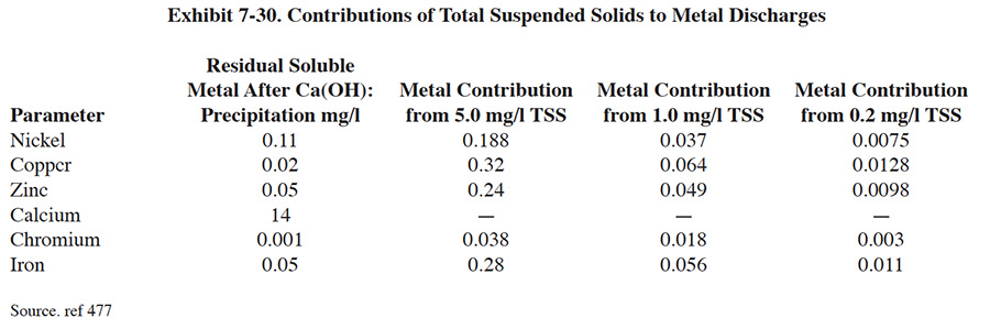 |
7.5.3.2 Development and Commercialization
The development and commercialization of membrane filtration is reviewed in Section 5.3. The literature indicates that in 1988, more than 100 full-scale industrial end-of-pipe systems had been installed by Memtek, the leading manufacturing company of this technology. These systems ranged in capacity from 10 to 400 gpm and were installed in facilities in the following industries: electroplating, printed circuit board manufacturing, battery manufacturing and photographic processing. Projecting the results from the Users Survey to the entire electroplating population, the expected number of systems would be approximately 170 (based on 4 of 318 respondents with systems and a total U.S. plating population of 13,500 plants).
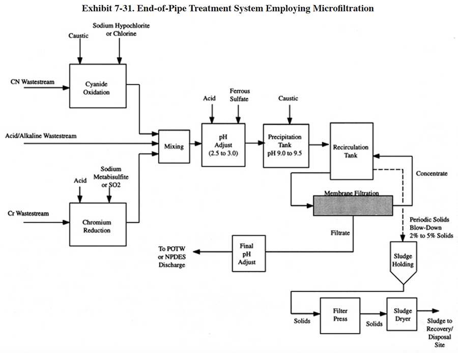 |
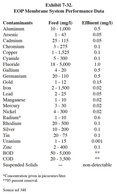 |
7.5.3.3 Applications and Restrictions
The general applications for this technology were discussed in Section 7.5.3.1. Exhibit 7-31 shows a generic EOP microfiltration system that could substitute for conventional treatment. For this application, the process chemistry will vary depending on the type and concentration of the constitutes in the feed stream and the target effluent levels. As discussed in Section 7.5.3.1, additional reagents may be used to enhance the precipitation of metals. Membrane system performance data from the literature, for this type of application, are presented in Exhibit 7-32.
The presence of oil and grease in the feed stream can cause fouling of the membrane. If present, additional pretreatment may be necessary. Most systems are installed with integral chemical cleaning systems that handle routine cleaning requirements. These systems are typically utilized once per week for a period of two hours (ref. 348).
7.5.3.4 Technology/Equipment Description
This subsection contains a description of commercially available microfiltration equipment that is manufactured and/or sold by vendor survey respondents. This is intended to provide the reader with information and data on a cross section of available equipment. Mention of trade names or commercial products is not intended to constitute endorsement for use.
Memtek Corporation manufactures complete end-of-pipe wastewater treatment systems that employ microfiltration for solids separation. These are modular systems to which various reactor skids (e.g., chromium reduction and cyanide oxidation) can be added, depending on the characteristics of the wastewater and the treatment requirements. For metals removal, precipitation is performed in a reactor/recirculation tank and the mixture of particles and water are pumped through the membrane filtration tubes at 40 to 50 psi and back to the reactor/recirculation tank. The filtrate passes through the pores of the filter to a final neutralization tank. Concentrated solids (2% to 5%) are periodically drawn from the reactor/recirculation tank to a sludge holding tank and subsequently dewatered.
The Memtek filtration membranes are contained in one-inch diameter porous plastic tubes. The membrane has uniform 0.1 micron pores that are funnel-shaped to minimize clogging. Filtration rates range up to 200 GFD. The membrane is chemically resistant to both acid and bleach cleaning solutions (ref. Memtek file). Every system includes a cleaning loop, consisting of a pump, tanks and the necessary piping and valving to permit in-place cleaning of the modules.
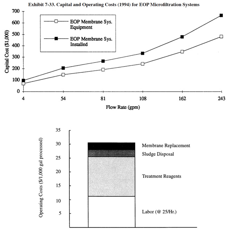 |
7.5.3.5 Costs
7.5.3.5.1 Capital Costs
Capital costs for end-of-pipe membrane filtration systems are presented in Exhibit 7-33. These systems include a two-tank reactor skid for pretreatment, filtration reactor skid and final pH adjustment skid. Installation costs (38% over basic equipment costs) include: engineering (10%), shipping (5%), piping (8%) and electrical/instrumentation (15%).
7.5.3.5.2 Operating Costs
Major operating costs for end-of-pipe systems that employ membrane filtration for solids separation are presented in Exhibit 7-33. The labor and chemical costs are based on the results from the Users Survey. Vendor data indicate that lower chemical costs may be experienced. Data presented by Memtek show chemical costs of $2.26 to $4.95 per 1,000 gal for two EOP applications (ref. Memtek file).
7.5.3.6 Performance Experience
Available information and data from the Users Survey is presented in Exhibit 7-34. Available diagrams of the respondents' treatment systems are presented in Exhibits 7-35, 7-36 and 7-37.
Generally, plating shops using this technology were satisfied with its performance. The average satisfaction level of the four respondents is 3.75. Two of the shops indicated that failure of their treatment system resulted in a compliance excursion.
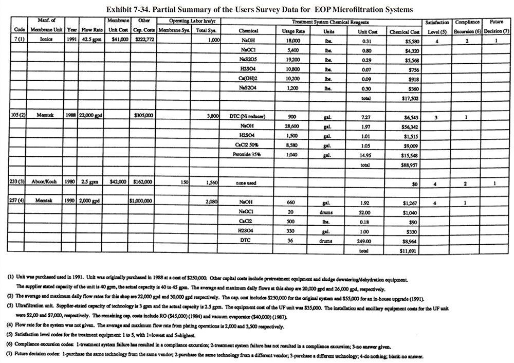 |
7.5.3.7 Operational and Maintenance Problems
Only one of the four respondents to the Users Survey that employ microfiltration for an EOP application reported any operational and maintenance problems. PS 105 reported that a rupture of their membrane occurred that resulted in a compliance excursion.
7.5.3.8 Residuals Generation
Membrane filtration, when used in an end-of-pipe treatment scheme, separates precipitated metals from the treated wastewater. The solids are subsequently dewatered and transported off-site as a hazardous waste (F006 or F019) for recovery or disposal. The mass (as dry solids) and characteristics of the sludge and its potential for recovery will depend on the characteristics of the original wastestream and the type of chemical reagents used in treatment. Membrane filtration, used as a substitute for clarification/thickening can be operated with conventional hydroxide precipitation reagents (e.g., caustic soda or lime). More often, due to the fact that membrane filtration is usually installed to meet stringent effluent limitations that cannot be attained with conventional clarification/thickening, additional treatment reagents are used to enhance the precipitation of metals, including the fraction that is normally soluble with the use of lime or caustic soda alone.
As shown in Exhibits 7-35 and 7-36, the two shops employing microfiltration as a substitute for clarification/thickening used additional reagents to supplement pre-cipitation. These additional reagents included ditho-carbamates (DTC) and lime. Ferrous sulfate and sodium sulfide, although not used by any of the respondents, are other reagents that are commonly used to enhance precipitation. The use of additional reagents, especially ferrous sulfate, will add to the mass of sludge generated by the treatment process. The use of sulfur based compounds will result in the generation of sulfide sludges and may reduce the potential of using off-site recycle as a disposal option.
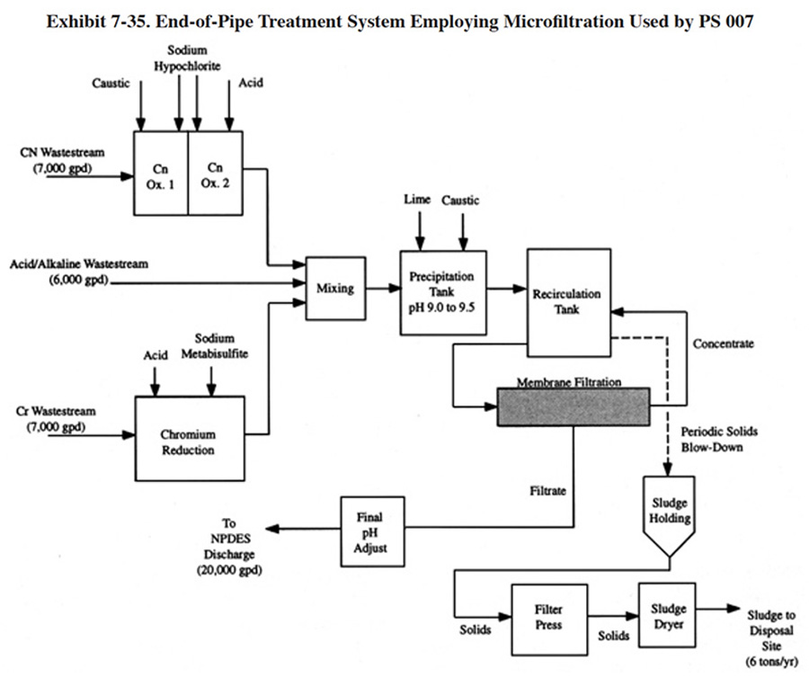 |
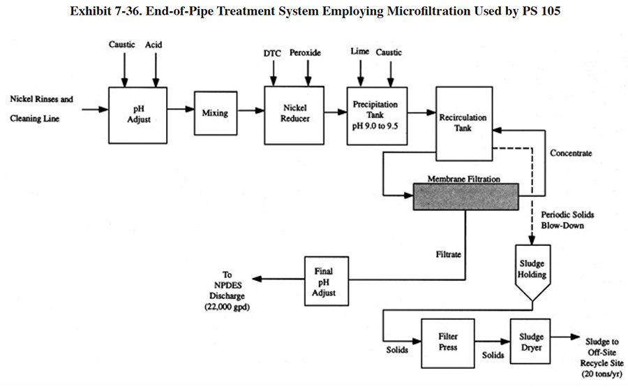 |
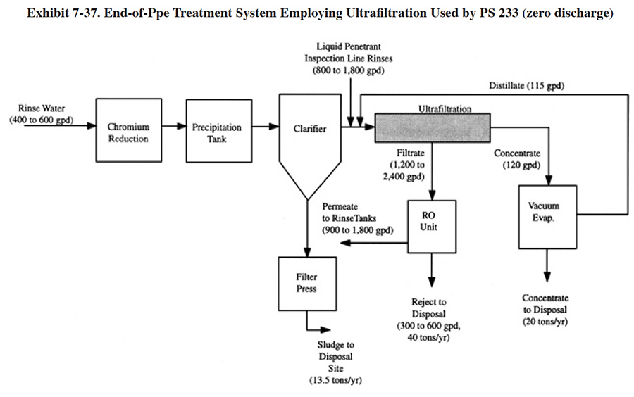 |
7.5.4 Evaporation
7.5.4.1 Overview
Evaporation is a commonly used technology for the recovery of plating chemicals from rinse waters, as discussed in Sections 4.2 and 4.3. In contrast, this section discusses the use of evaporation as an end-of-pipe technology. These applications are differentiated from those in Section 4 by the fact that no plating chemicals are recovered with the end-of-pipe applications. Rather, the evaporation technology is employed solely to reduce or eliminate the discharge of wastewater. It should be noted that several survey respondents used evaporation as a recovery technology and achieved zero-discharge (PS 071, PS 080, PS 193, PS 195). In three of these cases (all except PS 193), the evaporation needed to recover the rinse water/drag-out and attain zero-discharge was provided by heated process tanks (i.e., recovery rinsing). The fourth shop, PS 193, used atmospheric evaporators to provide the needed headroom in their process tanks (nickel and chrome plating) for attaining zero-discharge (their experience is discussed in Section 4.2).
A total of 8 (or 2.5%) of the respondents employ evaporation as an end-of-pipe technology. Of these eight respondents, seven have attained zero-discharge. The one plant with a discharge (PS 036) has an average daily discharge flow of 2,704 gpd. That shop indicated that they installed the evaporator as a treatment process for difficult to treat wastes (copper strip, mixed metal wastes and spent electroless nickel solution). Different types of equipment are used by the respondents, with vacuum evaporators being the most predominant. Five of the respondents use vacuum evaporators, two use atmospheric evaporators and one uses a boiler.
Most of the shops that attained zero-discharge did so recently. Four of the seven zero-discharge shops reached this goal in 1992. One shop reached zero-discharge in 1985, one in 1988 and the remaining shop did not indicate a date. All but one of these shops was discharging less than 1,000 gpd the year prior to reaching zero-discharge. The other shop appears to have jumped from 8,000 gpd to zero-discharge (PS 100). Several of the zero-discharge shops operated a limited number of plating processes. PS 282 and PS 006 only perform chromium plating and PS 021 performs chromium and electroless nickel plating. Only two of the shops gave any reasons for going to zero-discharge. One shop indicated that there was a $12,000 a year savings in self-monitoring costs. Another shop provided the following explanation (PS 202):
"To avoid ever increasing costs and goon squad regulation by the City of _____ Department of Sanitation-We severed our connection to the POTW. We recycle all rinse water that doesn't become contaminated. We use evaporation and a filter press to reduce waste to 55 gal DOT barrels and ship off-site for recycle. Crude-but effective for our operation."
7.5.4.2 Development and Commercialization
The development and commercialization of atmospheric and vacuum evaporators are discussed in Sections 4.2.2 and 4.3.2, respectively.
7.5.4.3 Applications and Restrictions
Four basic configurations of end-of-pipe evaporator use were employed by the eight survey respondents. These configurations are described in Exhibit 7-38. Application EVEOP-1 employs an atmospheric evaporator and there is no reuse of evaporated water. The other three configurations reuse the evaporated water for rinsing or, in the case of the boiler system (application EVEOP-4), the steam condensate is reused.
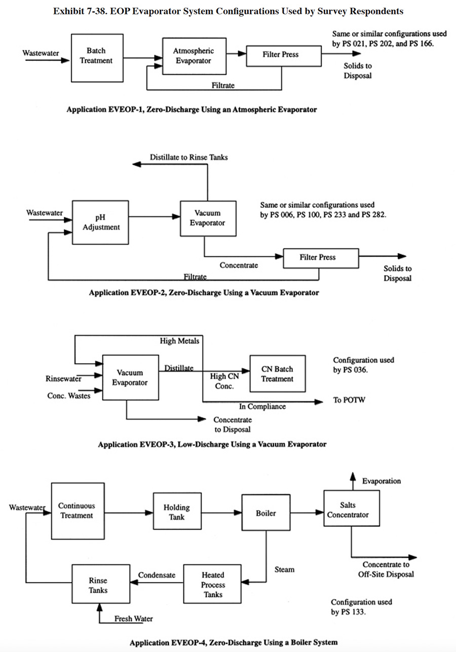 |
Evaporators not directly connected to a wastewater system may require a RCRA permit to operate them. Installation and operation of an atmospheric evaporator may require an air permit. Plating shops contemplating this type of treatment process should investigate the regulatory requirements for their specific application.
7.5.4.4 Technology/Equipment Description
This subsection contains references to commercially available evaporation equipment that is manufactured and/or sold by vendor survey respondents or identified during the literature search. This is intended to provide the reader with information and data on a cross section of available equipment. Mention of trade names or commercial products is not intended to constitute endorsement for use.
The evaporation equipment used for end-of-pipe treatment is usually the same equipment used for chemical recovery. Atmospheric and vacuum evaporation units are discussed in Sections 4.2.4 and 4.3.4. Some atmospheric and vacuum evaporation equipment is specifically designed for concentrating wastes. Applicable examples of atmospheric evaporation equipment include the Technotreat and SAMCO products discussed in Section 4.2.4. A type of vacuum evaporation equipment that is used for end-of-pipe treatment applications, but not usually applied to recovery, is the flash evaporator (e.g., LICON Flashvap). This equipment is discussed in Section 4.3.4.
7.5.4.5 Costs
Capital and operating costs for atmospheric and vacuum evaporators are presented in Sections 4.2.5 and 4.3.5. Capital costs can be expected to be approximately the same for recovery and end-of-pipe applications. In some circumstances, pretreatment of the feed stream may be warranted to prevent corrosion of the evaporator, necessitating additional tankage and chemical control equipment (e.g., pH control). Operating costs will be somewhat higher for end-of-pipe applications because solutions will typically be concentrated to a higher solids concentration in an effort to reduce the volume of concentrate produced and therefore lower off-site hauling costs. This will result in increased scaling within the evaporation unit and result in higher maintenance costs. These higher costs are specified in the operating costs for vacuum evaporators (Section 4.3.5.2).
7.5.4.6 Performance Experience
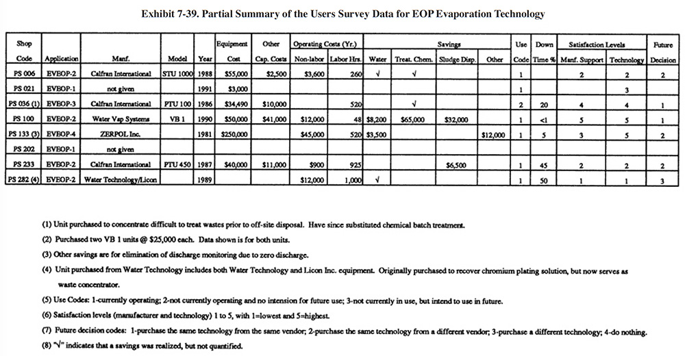 |
A summary of the Users Survey data is provided in Exhibit 7-39. The following information and data summarize the performance experience of the survey respondents.
- Shops using evaporation for end-of-pipe treatment gave mixed satisfaction levels for manufacturers' support and the technology itself. The low satisfaction level from PS 282 is mostly due to their inability to use their evaporator for chromium recovery. This problem may have been caused by an inappropriate selection of materials of construction. They stated: "The Water Technology system was purported to be a totally recyclable system, generating chrome acid concentrate back to the plating tank and distilled water. The chromic acid was contaminated and poisoned the plating baths. The fluoride catalyst attacks the titanium heat exchanger and the water sometimes gets contaminated with chrome. The system is a total nightmare."
- The following is a breakdown of the reasons why shops purchased this technology (includes data from six respondents):
To meet or help meet effluent regulations: 3
To reduce plating chemical purchases: 1
To reduce the quantity of waste shipped off-site: 3
To reduce wastewater treatment costs: 4
To improve product quantity: 1
Other: 0
- The use of evaporation had a little impact on production quality and the rate of production. The following responses were provided (includes data from six respondents):
Production Rate Product Quality
Improved 1 0
No Change 4 4
Decreased 1 1
- None of the shops indicated that evaporation applied as an end-of-pipe treatment method was the cause of an effluent compliance excursion (includes data from six respondents).
- Respondents reported operating cost savings from reduced water use, reduced treatment chemical use, reduced sludge disposal and from the elimination of discharge monitoring.
- PS 006 reported: "Unit will not process our effluent as well as Co [manufacturer/vendor] lead us to believe when purchasing unit. Technology was grossly oversold." The supplier stated capacity of the unit was 800 gal/24 hr and the actual capacity was 250 to 300 gal/24 hr.
- PS 233 reported that the supplier stated capacity of their unit was 450 gpd and that the actual capacity was 125 gpd.
7.5.4.7 Operational and Maintenance Problems
The following summarizes the respondent's O&M experiences and provides operating labor information.
- Five shops provided operating labor data. For these shops, the average number of annual operating hours per evaporator were: 468 hrs/yr (645 hr/yr excluding PS 100). The following is a breakdown of the responses for skill requirements (includes data from six respondents):
Environmental Engineer: 0
Process/Chemical Engineer: 0
Chemist: 0
Consultant: 0
Plumber/Pipe Fitter: 1
Electrician: 2
Vendor: 0
Senior-Level Plater: 3
Junior-Level Plater: 1
Trained Technician: 4
Wastewater Treatment Plant Operator: 2
Common Labor: 0
Other: 0
- PS 133 reported that use of their boiler for end-of-pipe treatment has resulted in the need to replace it.
- PS 036 indicated that ammonia, contained in their spent copper strip and electroless nickel solutions, is found in their distillate and that a second pass through the evaporator is necessary for complete removal.
- PS 282 reported: "Maintenance nightmare. No support from vendor-screwed up plating baths for at least one year."
- PS 233 reported: "Material failure: i.e., valves, piping, seals, vacuum pump, product pumps, refrigeration system, overflow protection."
7.5.4.8 Residuals Generation
Evaporators generate a concentrated waste product that can be directly shipped off-site for recovery or disposal or can be further processed (e.g., filter press) to increase its solids content. The concentration of solids from the discharge of the evaporator will depend on the type of unit selected. Common atmospheric evaporators used for chemical recovery are unable to concentrate waste much beyond typical plating bath strength. Some vacuum evaporators, such as the climbing film type, can achieve concentrations of 500,000 mg/l or more. Residuals data provided by respondents using evaporation as an end-of-pipe technology are shown in Exhibit 7-40.
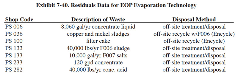 |
 |
 |
 |
The information contained in this site is provided for your review and convenience. It is not intended to provide legal advice with respect to any federal, state, or local regulation.
You should consult with legal counsel and appropriate authorities before interpreting any regulations or undertaking any specific course of action.
Please note that many of the regulatory discussions on STERC refer to federal regulations. In many cases, states or local governments have promulgated relevant rules and standards
that are different and/or more stringent than the federal regulations. Therefore, to assure full compliance, you should investigate and comply with all applicable federal, state and local regulations.